
manual
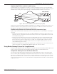
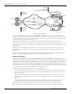


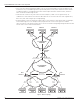


Table Of Contents
- Introduction
- Scope
- Design Considerations—Connectivity at the Branch Office
- Branch-Office Connectivity over IPsec VPN
- Design Recommendations
- Routing Information Protocol
- Traffic Load Balancing for Type B and Type C Branch Deployments
- Using Border Gateway Protocol for Large Networks
- Using OSPF for Small Number of Branch Offices
- Using Auto Connect VPN to Create Branch-to-Branch IPsec Tunnels
- High Availability for the Branch Office
- High Availability Requirement Levels (Link, Device, Device, and Link Levels)
- High Availability Functionalities
- High Availability for Branch Office Type A
- VPN Security Zone Configuration for Type A
- High Availability for Branch Office Type B
- Using Secure Services Gateway for Type B
- High Availabilty for Branch Office Type C
- Connectivity at the Data Center
- Implementing a High Availability Enterprise Network at the Data Center
- Quality of Service Design Requirements
- WX Design Requirements
- Summary
- Appendix A Related Documents
- Appendix B Naming Conventions
- Appendix C Products
- About Juniper Networks
- Figure 1: Connecting branch offices, campus locations, and data centers over a single converged network
- Figure 2: Branch office reference architecture
- Figure 3: Multi-tiered/layered network architecture
- Figure 4: Two-tier network design for data centers
- Figure 5: Branch with dual internet connections (load balancing using ECMP)
- Figure 6: BGP routing design
- Figure 7: Star topology – connecting branches to central hub
- Figure 8: AC VPN provisioned tunnels between branches in the same region
- Figure 9: Multi-tier topology
- Figure 10: HA configuration for Type A
- Figure 11: VPN security zone configuration for Type A
- Figure 12: Type B optimized – HA configuration
- Figure 13: Type B – security zones
- Figure 14: Type C – HA configuration
- Figure 15: Intra-branch using OSPF
- Figure 16: Branch Type C – security zones
- Figure 17: Enterprise network for the data center
- Figure 18: M Series Multiservice Edge Routers
- Figure 19: Internet firewalls
- Figure 20: VPN firewalls
- Figure 21: VPN firewall IPS policy
- Figure 2: Branch office reference architecture
16 Copyright © 2010, Juniper Networks, Inc.
APPLICATION NOTE - Branch Office Connectivity Guide
There is no session or configuration synchronization between the SSG Series Secure Services Gateways. Session
persistence happens by disabling TCP SYN checks when flows are created inside IPsec tunnels. In this way,
when traffic is rerouted to the secondary SSG Series, a new session is created and the traffic is forwarded to the
destination. Note that this does not represent a security vulnerability point because SYN checks are enabled at the
remote end of the tunnels.
It is important to understand that policies allowing traffic from the trust zone to the VPN zone (see Figure 13) have
to be mirrored in the opposite direction (that is from VPN to the trust zone). When traffic is forwarded over a failover
device, retry packets might originate only from the VPN zone to the trust zone (depending on the nature of the
traffic). If policies do not allow this traffic, a new session is not created and traffic—from sessions created before the
failure—is dropped.
Note that mixed mode NSRP is used in this configuration. Because Interface Bridge 0 has a Virtual Security Interface
(VSI) (bridge 0:1) that is used as a default gateway, the egress interface used is either a tunnel interface (for VPN
traffic) or a non-VSI Ethernet interface for Internet traffic.
Figure 13: Type B – security zones
For HA deployment at branch office Type B, refer to Implementing High Availability at the Branch Office.
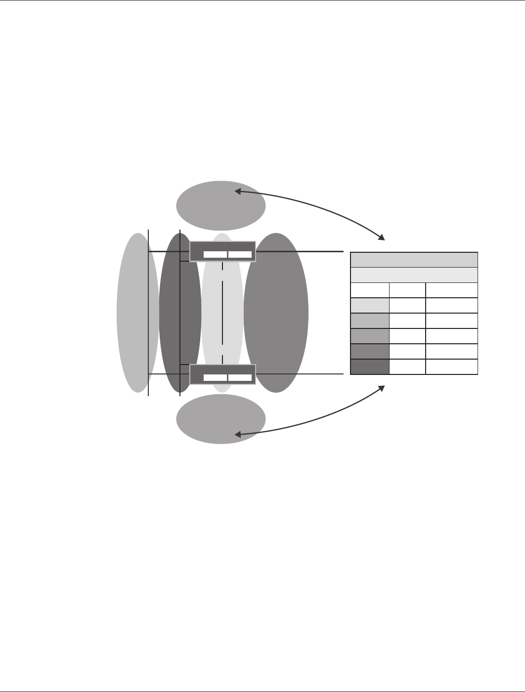
High Availabilty for Branch Office Type C
Medium- to large-sized branch offices use the Type C branch office configuration. This type of configuration provides
session redundancy with session replication, as well as traffic load balancing when multiple connections to the same
network are used—for example, multiple Internet connections. Figure 14 shows the HA configuration for branch
office Type C.
192.168.12.0/24
1.140.1.0/24
HA-link
e0/9:
e0/9:1
SSG Series
SSG Series
172.18.20.5
loopback. 1
172.18.1.2/32
loopback. 2.1
1.4.17.32/32
s1/0
172.18.0.253
e0/0
Tunnel.1 10.255.1.20
Tunnel.2 10.255.5.20
Tunnel.1 10.255.1.20
Tunnel.2 10.255.5.20
Legend
Zone
Color Count Description
1 Sync
1 Guest
2 VPN
1 Untrust
1 Trust
e0/4
e0/4