
manual
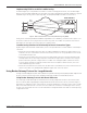
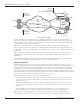


Table Of Contents
- Introduction
- Scope
- Design Considerations—Connectivity at the Branch Office
- Branch-Office Connectivity over IPsec VPN
- Design Recommendations
- Routing Information Protocol
- Traffic Load Balancing for Type B and Type C Branch Deployments
- Using Border Gateway Protocol for Large Networks
- Using OSPF for Small Number of Branch Offices
- Using Auto Connect VPN to Create Branch-to-Branch IPsec Tunnels
- High Availability for the Branch Office
- High Availability Requirement Levels (Link, Device, Device, and Link Levels)
- High Availability Functionalities
- High Availability for Branch Office Type A
- VPN Security Zone Configuration for Type A
- High Availability for Branch Office Type B
- Using Secure Services Gateway for Type B
- High Availabilty for Branch Office Type C
- Connectivity at the Data Center
- Implementing a High Availability Enterprise Network at the Data Center
- Quality of Service Design Requirements
- WX Design Requirements
- Summary
- Appendix A Related Documents
- Appendix B Naming Conventions
- Appendix C Products
- About Juniper Networks
- Figure 1: Connecting branch offices, campus locations, and data centers over a single converged network
- Figure 2: Branch office reference architecture
- Figure 3: Multi-tiered/layered network architecture
- Figure 4: Two-tier network design for data centers
- Figure 5: Branch with dual internet connections (load balancing using ECMP)
- Figure 6: BGP routing design
- Figure 7: Star topology – connecting branches to central hub
- Figure 8: AC VPN provisioned tunnels between branches in the same region
- Figure 9: Multi-tier topology
- Figure 10: HA configuration for Type A
- Figure 11: VPN security zone configuration for Type A
- Figure 12: Type B optimized – HA configuration
- Figure 13: Type B – security zones
- Figure 14: Type C – HA configuration
- Figure 15: Intra-branch using OSPF
- Figure 16: Branch Type C – security zones
- Figure 17: Enterprise network for the data center
- Figure 18: M Series Multiservice Edge Routers
- Figure 19: Internet firewalls
- Figure 20: VPN firewalls
- Figure 21: VPN firewall IPS policy
- Figure 2: Branch office reference architecture
Copyright © 2010, Juniper Networks, Inc. 15
APPLICATION NOTE - Branch Office Connectivity Guide
is routed through interface Ethernet 0/1, the interface IP address is used to NAT the traffic. In this way, there is no
need to propagate the addresses between service providers. In addition, DSL connections are supported because it is
not necessary to know the IP address assigned to each of the Internet-connected interfaces in advance. Instead, the
Dynamic Host Configuration Protocol (DHCP) is used in this case.
For deploying HA at branch office Type A, see Implementing High Availability (HA) at the Branch Office.
High Availability for Branch Office Type B
The branch office Type B uses two firewall devices that are connected to two different networks, such as a Peer-
to-Peer (PTP) network and the Internet. IPsec tunnels are configured to each data center using both networks in
a similar fashion like branch office Type A. The difference is that the metrics are lower on the tunnel interfaces
terminating the IPsec tunnels that transverse the PTP network. Thus, whenever possible, the PTP network carries
traffic going to and from the data centers.
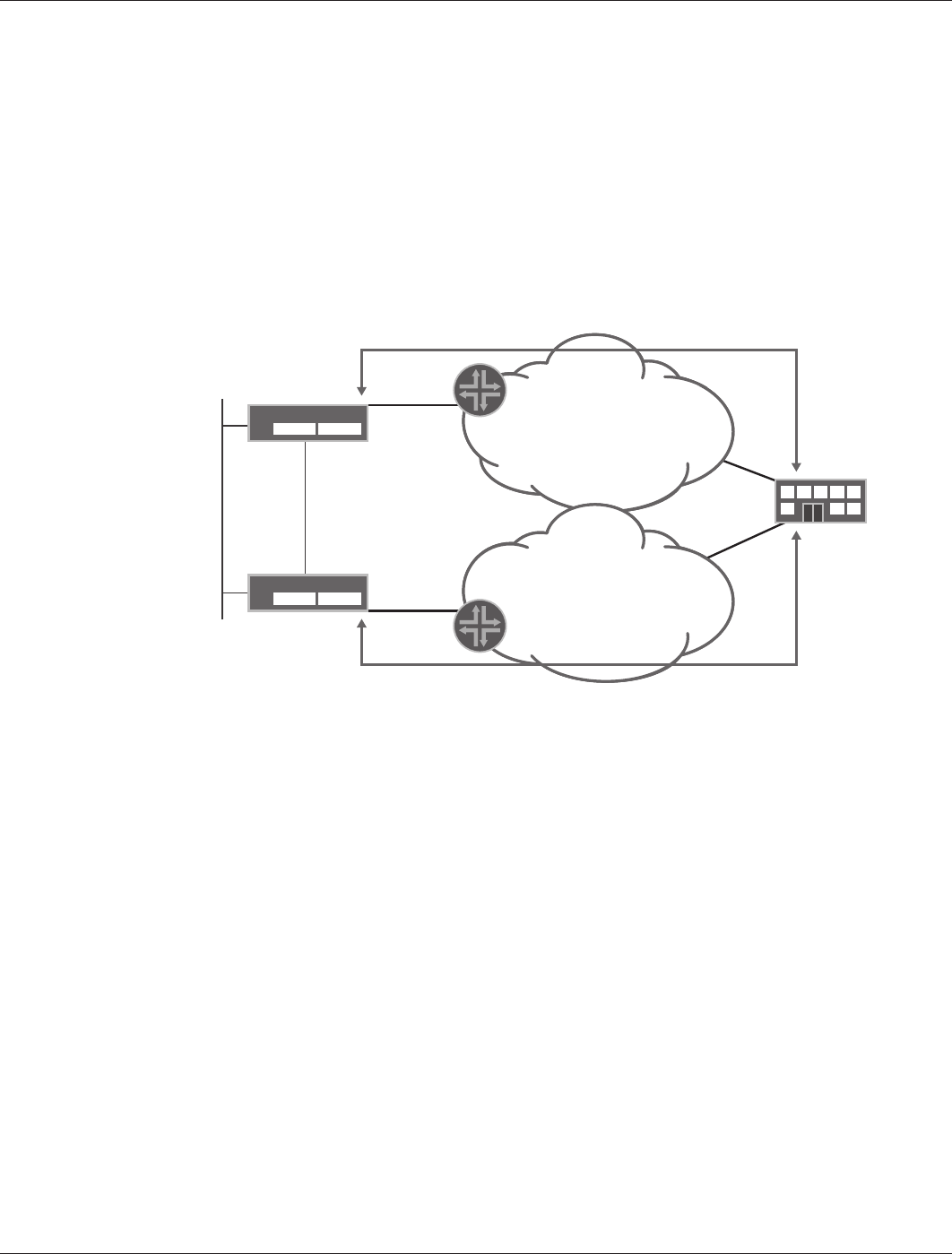
Figure 12 shows the HA configuration for branch office Type B.
Figure 12: Type B optimized – HA configuration
Using Secure Services Gateway for Type B
For branch office Type B, each Juniper Networks SSG Series Secure Services Gateway terminates a pair of tunnels
(one to each data center), as each is connected to a different network. Both devices are constantly active, but the
NSRP is used in the trust (and guest) interfaces to direct the traffic to the SSG Series that connects to the PTP
network. NSRP is configured in such a way that whenever a tunnel fails, NSRP fails over to the SSG Series terminating
tunnels routed through the Internet. In this way, the PTP network is preferred over the Internet if the tunnels are
active. Whenever a tunnel fails at any of the data centers, traffic is rerouted to the secondary SSG Series gateway.
Whenever the primary SSG Series is active, Internet traffic is routed using the Ethernet interface connecting both
SSG Series Secure Services Gateways (belonging to the sync zone). Traffic, in turn, is NATed to the egress interface
address on the ISP that connects the SSG Series (1.4.0.253 in this example).
The PTP network is used to back up the Internet connection whenever the link between the SSG Series and the
Internet fails. One of the data centers advertises a default route over the PTP-transported IPsec tunnels. A default
route is also advertised by the SSG Series to its neighbor over the Ethernet that is connecting them (Ethernet 0/1
in our example). In this manner, when the connection between the SSG Series and the Internet fails, the other SSG
Series prefers the default route received through IPsec and sends all of its Internet traffic to the data center.
Because addresses in the PTP network are known in advance, a tunnel terminating at the primary SSG Series uses
main mode and identifies the IPsec peers by their remote IP address. Instead, tunnels routed through the Internet
use aggressive mode and IDs identify peers.
172.18.20.5
e0/0
1.4.0.253
e0/0
172.18.20.4
1.4.0.1
1.2.0.6
172.18.8.162
SSG Series
SSG Series
DATA
CENTER A
10.255.5.0/24
10.255.1.0/24
1.20.2.0/24
INTERNET
PTP NETWORK
b0:1
b0:1
192.168.100.1
e0/1
192.168.100.1
e0/1
10.255.5.20
Tunnel 5
10.255.1.20
Tunnel 1
10.255.5.254
Tunnel 5
10.255.1.254
Tunnel 1