
manual
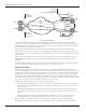


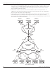


Table Of Contents
- Introduction
- Scope
- Design Considerations—Connectivity at the Branch Office
- Branch-Office Connectivity over IPsec VPN
- Design Recommendations
- Routing Information Protocol
- Traffic Load Balancing for Type B and Type C Branch Deployments
- Using Border Gateway Protocol for Large Networks
- Using OSPF for Small Number of Branch Offices
- Using Auto Connect VPN to Create Branch-to-Branch IPsec Tunnels
- High Availability for the Branch Office
- High Availability Requirement Levels (Link, Device, Device, and Link Levels)
- High Availability Functionalities
- High Availability for Branch Office Type A
- VPN Security Zone Configuration for Type A
- High Availability for Branch Office Type B
- Using Secure Services Gateway for Type B
- High Availabilty for Branch Office Type C
- Connectivity at the Data Center
- Implementing a High Availability Enterprise Network at the Data Center
- Quality of Service Design Requirements
- WX Design Requirements
- Summary
- Appendix A Related Documents
- Appendix B Naming Conventions
- Appendix C Products
- About Juniper Networks
- Figure 1: Connecting branch offices, campus locations, and data centers over a single converged network
- Figure 2: Branch office reference architecture
- Figure 3: Multi-tiered/layered network architecture
- Figure 4: Two-tier network design for data centers
- Figure 5: Branch with dual internet connections (load balancing using ECMP)
- Figure 6: BGP routing design
- Figure 7: Star topology – connecting branches to central hub
- Figure 8: AC VPN provisioned tunnels between branches in the same region
- Figure 9: Multi-tier topology
- Figure 10: HA configuration for Type A
- Figure 11: VPN security zone configuration for Type A
- Figure 12: Type B optimized – HA configuration
- Figure 13: Type B – security zones
- Figure 14: Type C – HA configuration
- Figure 15: Intra-branch using OSPF
- Figure 16: Branch Type C – security zones
- Figure 17: Enterprise network for the data center
- Figure 18: M Series Multiservice Edge Routers
- Figure 19: Internet firewalls
- Figure 20: VPN firewalls
- Figure 21: VPN firewall IPS policy
- Figure 2: Branch office reference architecture
14 Copyright © 2010, Juniper Networks, Inc.
APPLICATION NOTE - Branch Office Connectivity Guide
Functionality Description
Network Address
Translation (NAT)
NAT is enabled so that machines in the trusted and guest zones can access the
Internet. In the event of a failure, Internet sessions might not be preserved as the
translated addresses of that traffic might have to change and different service
providers might be used on the Internet links.
Fast failover times Whenever failures occur (link, device, or data center failures), traffic should be
rerouted in less than 30 seconds. Within this time, packet loss might occur, but
sessions will be maintained if the user applications can withstand these failover times.
Secure management
traffic
SNMP is enabled through the IPsec tunnels. Whenever backup devices are provided for
branches Type B and Type C, it is possible to monitor both devices—even if one of them
is not forwarding traffic (nor terminating any IPsec tunnel).
High Availability for Branch Office Type A
To implement HA, the best practice calls for each Type A branch office to employ two Internet connections and four
tunnels (two per each data center). Traffic is load-balanced across each pair of tunnels. That is, whenever traffic is
directed to a given data center, sessions are load-balanced in a round-robin fashion across each IPsec tunnel going
to that data center. In turn, the tunnels are configured so that each tunnel uses a different egress link, resulting in a
limited HA configuration for this branch office type.
Figure 11 shows as an example, branch office Type A HA configuration with dual Internet connections to a single data
center. Note, that although multiple data centers might be used, from the branch HA perspective, the configuration
is identical. Only the IPsec tunnel configurations and routing have changed. For further details, refer to the
Implementing IPsec VPN for Branch Office Connectivity Using RIP application note.
Figure 10: HA configuration for Type A
VPN Security Zone Configuration for Type A
Figure 11 shows the VPN security zone configuration. VPN tunnels are part of a separate zone named the “VPN
zone.” Implementing a VPN zone is an important consideration when designing security policies, as traffic going to
the data centers (or other branches) will exit through this security zone.
Figure 11: VPN security zone configuration for Type A
For Type A, NAT is provided based on the egress interface. That is, whenever traffic is routed through interface
Ethernet 0/0, traffic is NATed using the interface’s IP address as the source address (which is assigned by an Internet
service provider (ISP) and possibly different than the one used in interface Ethernet 0/1). Similarly, whenever traffic
1.2.1.252
e0/0
1.4.0.253
e0/0
1.2.1.1
1.4.0.1
1.2.0.6
1.3.0.6
SSG Series
Static Routers
1.2.0.6 via 1.4.0.1
1.3.0.6 via 1.4.0.1
DATA CENTER A
10.255.1.0/24
10.255.2.0/24
1.5.1.0/24
INTERNET
b0
10.5.1.0/24
IPsec to
Data Center A
IPsec to
Data Center A
Legend
Zone
Color Count Description
4 VPN
2 Untrust
2 Trust
SSG Series
To ISP
To ISP
1.2.1.252
e0/1
1.2.1.252
e0/0
10.255.2.1
tunnel 1
10.255.2.1
tunnel 2
VPN