
manual
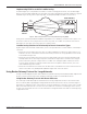
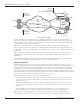


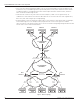


Table Of Contents
- Introduction
- Scope
- Design Considerations—Connectivity at the Branch Office
- Branch-Office Connectivity over IPsec VPN
- Design Recommendations
- Routing Information Protocol
- Traffic Load Balancing for Type B and Type C Branch Deployments
- Using Border Gateway Protocol for Large Networks
- Using OSPF for Small Number of Branch Offices
- Using Auto Connect VPN to Create Branch-to-Branch IPsec Tunnels
- High Availability for the Branch Office
- High Availability Requirement Levels (Link, Device, Device, and Link Levels)
- High Availability Functionalities
- High Availability for Branch Office Type A
- VPN Security Zone Configuration for Type A
- High Availability for Branch Office Type B
- Using Secure Services Gateway for Type B
- High Availabilty for Branch Office Type C
- Connectivity at the Data Center
- Implementing a High Availability Enterprise Network at the Data Center
- Quality of Service Design Requirements
- WX Design Requirements
- Summary
- Appendix A Related Documents
- Appendix B Naming Conventions
- Appendix C Products
- About Juniper Networks
- Figure 1: Connecting branch offices, campus locations, and data centers over a single converged network
- Figure 2: Branch office reference architecture
- Figure 3: Multi-tiered/layered network architecture
- Figure 4: Two-tier network design for data centers
- Figure 5: Branch with dual internet connections (load balancing using ECMP)
- Figure 6: BGP routing design
- Figure 7: Star topology – connecting branches to central hub
- Figure 8: AC VPN provisioned tunnels between branches in the same region
- Figure 9: Multi-tier topology
- Figure 10: HA configuration for Type A
- Figure 11: VPN security zone configuration for Type A
- Figure 12: Type B optimized – HA configuration
- Figure 13: Type B – security zones
- Figure 14: Type C – HA configuration
- Figure 15: Intra-branch using OSPF
- Figure 16: Branch Type C – security zones
- Figure 17: Enterprise network for the data center
- Figure 18: M Series Multiservice Edge Routers
- Figure 19: Internet firewalls
- Figure 20: VPN firewalls
- Figure 21: VPN firewall IPS policy
- Figure 2: Branch office reference architecture

Copyright © 2010, Juniper Networks, Inc. 13
APPLICATION NOTE - Branch Office Connectivity Guide
• A single NHS server only can be configured on a per-client basis. During a complete failure at the hub (either
data center or regional office acting as an NHS), branch offices cannot establish shortcuts until connectivity to
the hub is restored.
• A new registration to the NHS is required when an NSRP failover is triggered. If a failover occurs at one of the
hubs, then every branch office has to reregister and the NHRP cache has to be repopulated.
• The NHRP is not supported over unnumbered interfaces.
High Availability for the Branch Office
Branch office HA is a key design concern that assures business continuity for the branch offices. Juniper implements
branch office HA by using link, device, or a combination of link and device redundancy to ensure network availability.
Juniper offers three types of configurations, differing only by the branch office profiles. The result is a high availability
enterprise network that can reliably connect the branch office locations to the data centers.
High Availability Requirement Levels (Link, Device, Device and Link Levels)
When defining HA, first you must identify the level of HA required for each branch office. The three levels of high
availability include:
• Link-Level HA: This requires two links to operate in an active backup setting so if one link fails, the other takes
over (or likely reinstates) the forwarding of traffic that has been previously forwarded over the failed link.
• Device-Level HA: This means effectively doubling up on devices to assure there is a backup device to take over
for a failed device in such an event. Typically, the link redundancy and device redundancy are coupled, which
effectively ties failures together.
• Device- and Link-Level HA: This allows a device to fail without requiring the respective link to fail. Note that
there still will be a device attached to each link, and if that device fails, a link failure may occur as well. However,
not every device failure will cause a link failure.
High Availability Functionalities
Juniper Networks Enterprise Framework and Branch Office Reference Architecture documents present the framework
for this solution. Table 2 summarizes the key HA design functionalities that are used as a basis for branch office HA
design recommendations.
Table 2: HA Functionalities
Functionality Description
Link failure protection Failure on any given access link should not result in connectivity loss. This only applies
to branch offices with at least two upstream links connected either to a private network
or to the Internet.
Device failure
protection
No single device failure should result in connectivity loss from the branch office to the
data centers (except for Type A branch offices, which do not provide redundant devices).
However, a failure in a device might result in Internet connectivity loss if only one
Internet connection is used.
Data center failure
protection
In the event of a complete failure in one of the data centers, traffic must be rerouted to
a backup data center, as data centers share a point-to-point connection.
Session persistence Branch offices with redundant devices should provide session persistence. That is, in
the event of a failure, established sessions should not be dropped, even if traffic was
being forwarded by the failed device.
Load balancing Customer traffic is balanced across dual connections to the data center. If a link fails,
all traffic is directed through the remaining link.
Traffic symmetry UTM features and firewalling are enabled at the branches. For these to work, this
design guarantees that both ingress and egress traffic flows traverse the same
firewall. The same scenario is implemented at the data centers.