
manual
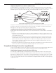
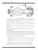


Table Of Contents
- Introduction
- Scope
- Design Considerations—Connectivity at the Branch Office
- Branch-Office Connectivity over IPsec VPN
- Design Recommendations
- Routing Information Protocol
- Traffic Load Balancing for Type B and Type C Branch Deployments
- Using Border Gateway Protocol for Large Networks
- Using OSPF for Small Number of Branch Offices
- Using Auto Connect VPN to Create Branch-to-Branch IPsec Tunnels
- High Availability for the Branch Office
- High Availability Requirement Levels (Link, Device, Device, and Link Levels)
- High Availability Functionalities
- High Availability for Branch Office Type A
- VPN Security Zone Configuration for Type A
- High Availability for Branch Office Type B
- Using Secure Services Gateway for Type B
- High Availabilty for Branch Office Type C
- Connectivity at the Data Center
- Implementing a High Availability Enterprise Network at the Data Center
- Quality of Service Design Requirements
- WX Design Requirements
- Summary
- Appendix A Related Documents
- Appendix B Naming Conventions
- Appendix C Products
- About Juniper Networks
- Figure 1: Connecting branch offices, campus locations, and data centers over a single converged network
- Figure 2: Branch office reference architecture
- Figure 3: Multi-tiered/layered network architecture
- Figure 4: Two-tier network design for data centers
- Figure 5: Branch with dual internet connections (load balancing using ECMP)
- Figure 6: BGP routing design
- Figure 7: Star topology – connecting branches to central hub
- Figure 8: AC VPN provisioned tunnels between branches in the same region
- Figure 9: Multi-tier topology
- Figure 10: HA configuration for Type A
- Figure 11: VPN security zone configuration for Type A
- Figure 12: Type B optimized – HA configuration
- Figure 13: Type B – security zones
- Figure 14: Type C – HA configuration
- Figure 15: Intra-branch using OSPF
- Figure 16: Branch Type C – security zones
- Figure 17: Enterprise network for the data center
- Figure 18: M Series Multiservice Edge Routers
- Figure 19: Internet firewalls
- Figure 20: VPN firewalls
- Figure 21: VPN firewall IPS policy
- Figure 2: Branch office reference architecture
12 Copyright © 2010, Juniper Networks, Inc.
APPLICATION NOTE - Branch Office Connectivity Guide
• The security associations (SAs) and the NHRP caches are not synchronized when active/active NSRP is used.
If a failover occurs, a new NHRP registration is performed, and as a result, branch-to-branch tunnels must be
reestablished. However, reestablishment of tunnels will not impact the branch-to-branch traffic, as branch
traffic still will be routed through the hub.
• The branch offices that are only connected to the same hub (that is, a data center or regional office) can
establish IPsec shortcuts between themselves. When branches are not connected to the same regional office/
data center, traffic flows using the pre-existing topology.
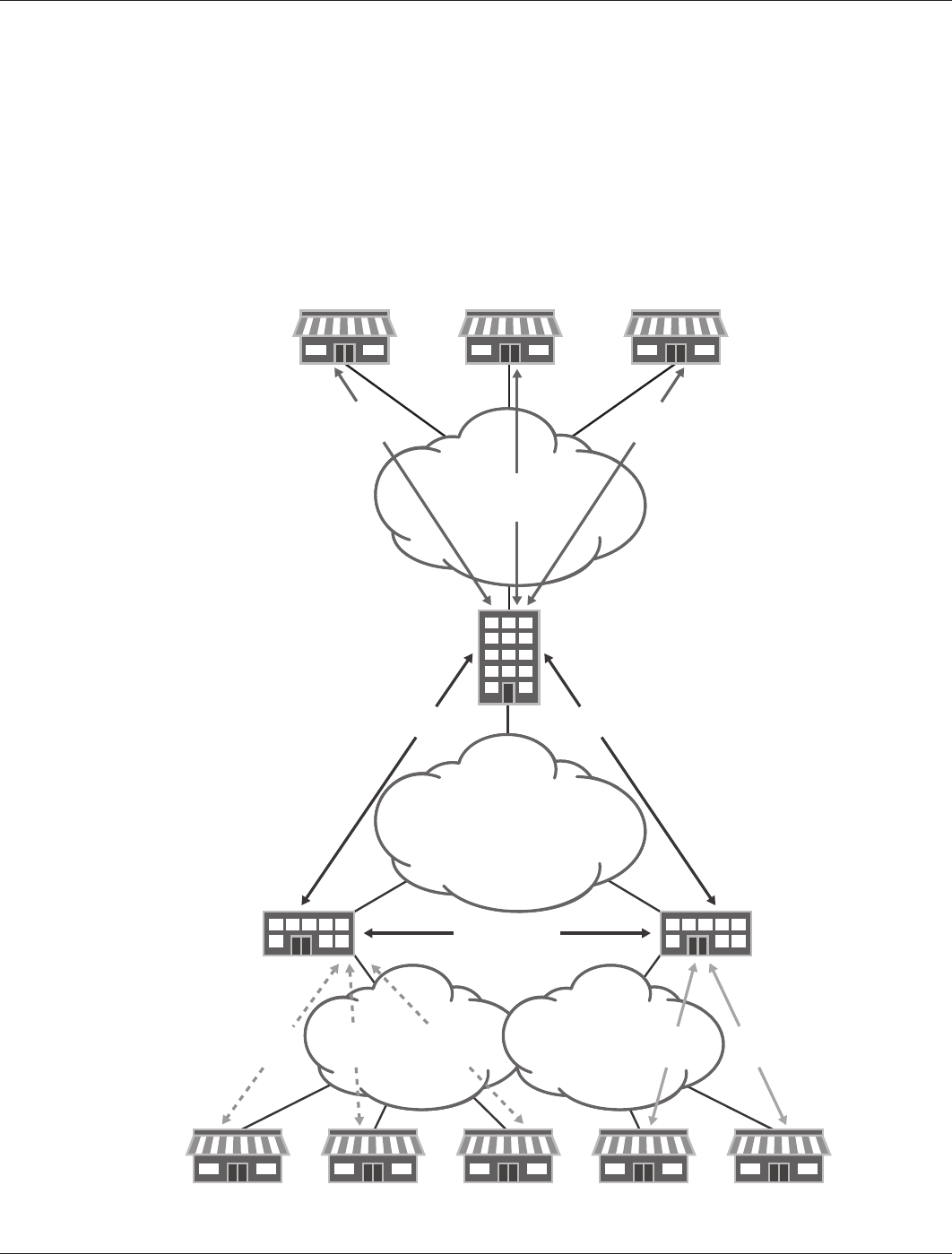
• AC VPN establishes shortcuts only between branch offices connected to the same hub for multi-tier topologies,
as illustrated in Figure 9. In the example network, only branch offices in the same region can establish
shortcuts. However, traffic between branch offices still can use normal routing and go through the different hubs
until the traffic reaches the desired destination.
Figure 9: Multi-tier topology
BRANCH 1
BRANCH BRANCH BRANCH BRANCH BRANCH
BRANCH 2 BRANCH N
DATA
CENTER B
DATA
CENTER A
REGIONAL
OFFICE
IPsec
Tunnel
IPsec
Tunnel
PTP NETWORK/
INTERNET
IPsec Tunnel
or PTP Connection
IPsec Tunnel
or PTP Connection
IPsec Tunnel
or PTP Connection
IPsec
Tunnel
IPsec
Tunnel
IPsec
Tunnel
IPsec
Tunnel
IPsec
Tunnel
PTP NETWORK/
INTERNET