
manual
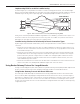
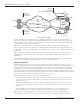


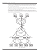


Table Of Contents
- Introduction
- Scope
- Design Considerations—Connectivity at the Branch Office
- Branch-Office Connectivity over IPsec VPN
- Design Recommendations
- Routing Information Protocol
- Traffic Load Balancing for Type B and Type C Branch Deployments
- Using Border Gateway Protocol for Large Networks
- Using OSPF for Small Number of Branch Offices
- Using Auto Connect VPN to Create Branch-to-Branch IPsec Tunnels
- High Availability for the Branch Office
- High Availability Requirement Levels (Link, Device, Device, and Link Levels)
- High Availability Functionalities
- High Availability for Branch Office Type A
- VPN Security Zone Configuration for Type A
- High Availability for Branch Office Type B
- Using Secure Services Gateway for Type B
- High Availabilty for Branch Office Type C
- Connectivity at the Data Center
- Implementing a High Availability Enterprise Network at the Data Center
- Quality of Service Design Requirements
- WX Design Requirements
- Summary
- Appendix A Related Documents
- Appendix B Naming Conventions
- Appendix C Products
- About Juniper Networks
- Figure 1: Connecting branch offices, campus locations, and data centers over a single converged network
- Figure 2: Branch office reference architecture
- Figure 3: Multi-tiered/layered network architecture
- Figure 4: Two-tier network design for data centers
- Figure 5: Branch with dual internet connections (load balancing using ECMP)
- Figure 6: BGP routing design
- Figure 7: Star topology – connecting branches to central hub
- Figure 8: AC VPN provisioned tunnels between branches in the same region
- Figure 9: Multi-tier topology
- Figure 10: HA configuration for Type A
- Figure 11: VPN security zone configuration for Type A
- Figure 12: Type B optimized – HA configuration
- Figure 13: Type B – security zones
- Figure 14: Type C – HA configuration
- Figure 15: Intra-branch using OSPF
- Figure 16: Branch Type C – security zones
- Figure 17: Enterprise network for the data center
- Figure 18: M Series Multiservice Edge Routers
- Figure 19: Internet firewalls
- Figure 20: VPN firewalls
- Figure 21: VPN firewall IPS policy
- Figure 2: Branch office reference architecture
Copyright © 2010, Juniper Networks, Inc. 11
APPLICATION NOTE - Branch Office Connectivity Guide
Note: The hub also stores a profile with the configuration of the IPsec tunnels that branch offices use to achieve
connectivity. This way, the configuration is simplified, as the tunnels only have to be configured on the hub. This
configuration is then pushed to the spokes whenever a direct IPsec VPN connection is established.
The Tunnel-Building Process
Once the registration process is finalized, the branch offices start building tunnels (Figure 8) between themselves
as follows:
• A branch office has traffic to send to another branch office. Normal IP routing occurs and the traffic is sent to
the hub so that this traffic can then be forwarded to the destination branch.
• The hub VPN concentrator forwards the packet and it notifies the NHRP module that there is traffic going across
the hub from two networks that have mappings stored in the next-hop server (NHS) cache.
• The hub concentrator then sends an NHRP resolution packet to the branch, along with a mapping of the remote
branch office network, to its public IP address. In addition, the hub concentrator sends a hash of the certificate
that the remote branch uses to identify itself, and a profile describing the configuration of the IPsec tunnel that
each branch office should use.
• Note: This information is encrypted over the IPsec tunnels (established between the hub and spokes) so the
trust relationship has already been determined.
• The branch can update its NHRP cache information after receiving the mapping, and using this information,
establishes a tunnel to the remote branch.
• The two branches—after the tunnels have been established—add a route to the other’s branch network through
the newly created tunnel. These new tunnels are tagged as NHRP routes.
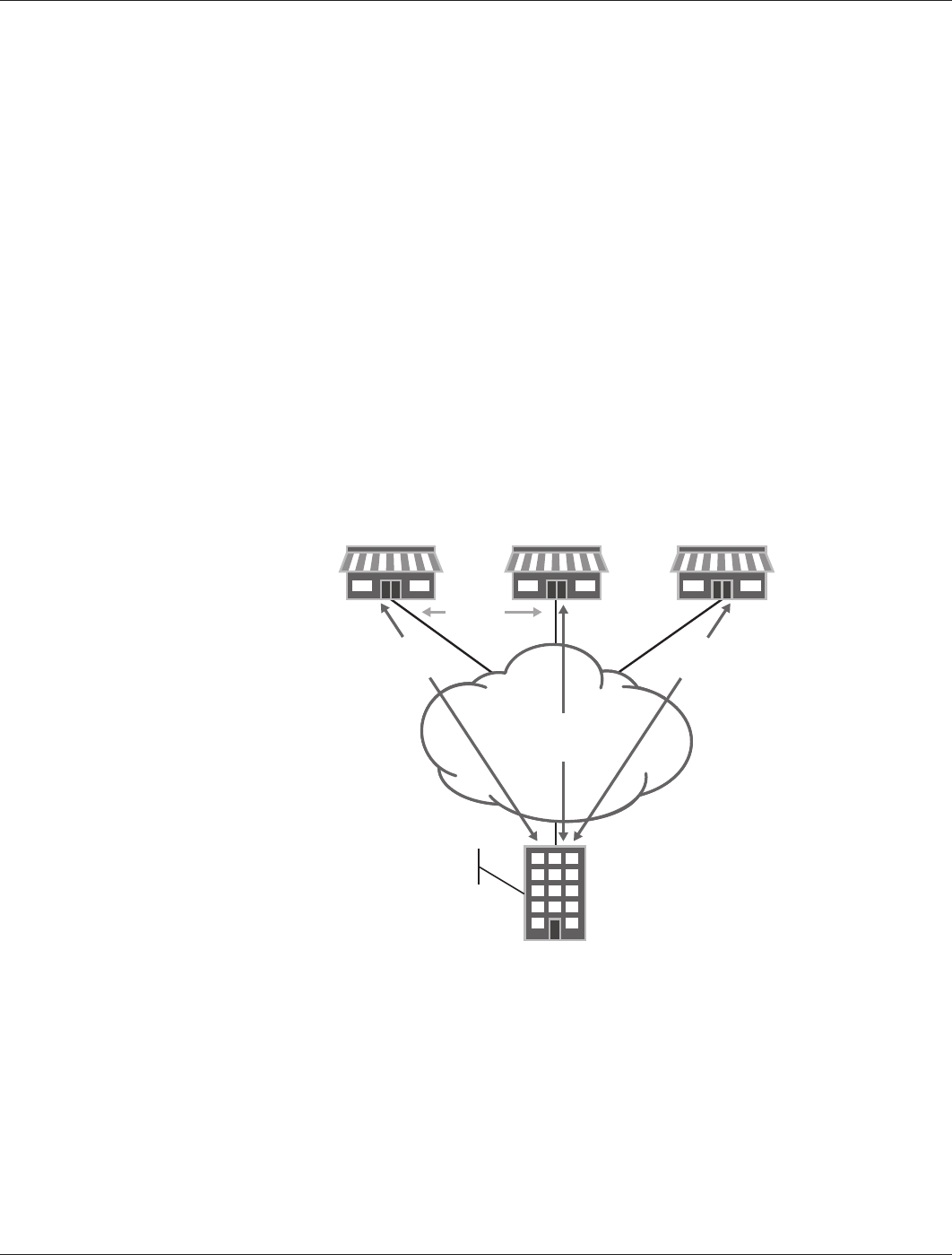
Figure 8: AC VPN provisioned tunnels between branches in the same region
Auto Connect VPN Design Considerations
The following are the design considerations and assumptions associated with this implementation.
• The NHS address must be the address of the tunnel interface terminating the IPsec tunnels from the branch
offices. In particular, the NHS will not detect requests on loopback interfaces.
• A device can only act as a next-hop client (NHC) or an NHS but not both because hierarchies are not supported.
• The Type B branch offices do not have AC VPN provided for the secondary device. During a failure, the AC VPN
service is not available and traffic is routed through the hub.
BRANCH 1 (NHC) BRANCH 2 (NHC) BRANCH N
REGIONAL
OFFICE
Manually
Configured
Tunnel
Manually
Configured
Tunnel
ACVPN
Provisioned
Tunnel
NHRP
Next Hop Server
PTP NETWORK/
INTERNET