
manual
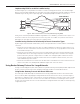
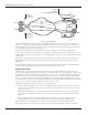


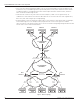


Table Of Contents
- Introduction
- Scope
- Design Considerations—Connectivity at the Branch Office
- Branch-Office Connectivity over IPsec VPN
- Design Recommendations
- Routing Information Protocol
- Traffic Load Balancing for Type B and Type C Branch Deployments
- Using Border Gateway Protocol for Large Networks
- Using OSPF for Small Number of Branch Offices
- Using Auto Connect VPN to Create Branch-to-Branch IPsec Tunnels
- High Availability for the Branch Office
- High Availability Requirement Levels (Link, Device, Device, and Link Levels)
- High Availability Functionalities
- High Availability for Branch Office Type A
- VPN Security Zone Configuration for Type A
- High Availability for Branch Office Type B
- Using Secure Services Gateway for Type B
- High Availabilty for Branch Office Type C
- Connectivity at the Data Center
- Implementing a High Availability Enterprise Network at the Data Center
- Quality of Service Design Requirements
- WX Design Requirements
- Summary
- Appendix A Related Documents
- Appendix B Naming Conventions
- Appendix C Products
- About Juniper Networks
- Figure 1: Connecting branch offices, campus locations, and data centers over a single converged network
- Figure 2: Branch office reference architecture
- Figure 3: Multi-tiered/layered network architecture
- Figure 4: Two-tier network design for data centers
- Figure 5: Branch with dual internet connections (load balancing using ECMP)
- Figure 6: BGP routing design
- Figure 7: Star topology – connecting branches to central hub
- Figure 8: AC VPN provisioned tunnels between branches in the same region
- Figure 9: Multi-tier topology
- Figure 10: HA configuration for Type A
- Figure 11: VPN security zone configuration for Type A
- Figure 12: Type B optimized – HA configuration
- Figure 13: Type B – security zones
- Figure 14: Type C – HA configuration
- Figure 15: Intra-branch using OSPF
- Figure 16: Branch Type C – security zones
- Figure 17: Enterprise network for the data center
- Figure 18: M Series Multiservice Edge Routers
- Figure 19: Internet firewalls
- Figure 20: VPN firewalls
- Figure 21: VPN firewall IPS policy
- Figure 2: Branch office reference architecture
10 Copyright © 2010, Juniper Networks, Inc.
APPLICATION NOTE - Branch Office Connectivity Guide
• Assumptions about the nature of the IPsec tunnels have not been made. Both aggressive and main mode
tunnels can be mixed on the presented network. If a failure occurs, when using the aggressive mode with
dynamic peers, only the remote peer can initiate a new IPsec tunnel connection. This might result in longer
recovery times.
• It is important to configure RIP using demand circuit extensions. Otherwise, the protocol overhead would be
large, as every branch office would retransmit its prefixes during every update interval (30 seconds by default).
For detailed instructions about using a RIP-based IPsec routing implementation, refer to the Implementing IPsec
VPN for Branch Office Connectivity Using RIP. Appendix C lists the product tables for the various Juniper Networks and
Juniper partner product solutions that support the design and deployment of high-performance enterprise networks.
Using Auto Connect VPN to Create Branch-to-Branch IPsec Tunnels
Juniper Networks developed the Auto Connect VPN (AC VPN) feature, which allows the dynamic creation of
branch-to-branch IPsec tunnels. These tunnels are created on an on-demand basis and are triggered by the traffic
generated at any given branch office. To accomplish this, AC VPN uses Next Hop Resolution Protocol (NHRP). This
protocol was originally developed for non-broadcast multiple access (NBMA) networks and is intended to provide a
discovery mechanism for stations to determine the L2 address of a device that connects to a particular L3 network
(or the egress router for that particular destination).
Next Hop Resolution Protocol
NHRP is reused and augmented to achieve a similar task—that is, to discover the public IP address of a VPN
termination endpoint. Whenever a branch office needs to send traffic to another branch office, this office can
establish an IPsec tunnel directly to the destination branch. To this effect, the branch originating the traffic can use
NHRP to discover the public IP address of the remote branch.
Some proprietary extensions have been added to the protocol and provide a way to simplify the provisioning of these
tunnels. Before presenting the details, it is important to understand the required base topology of the network for
compatibility with NHRP.
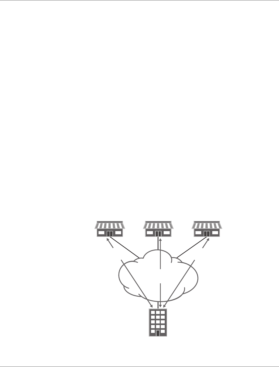
For AC VPN to work, it is necessary to have a star topology network that connects all the branches to a central
hub, as shown in Figure 7. The branch offices use these tunnels to register the networks directly connected to
each of them. The regional office stores (in a local database) a mapping of all the networks that each branch
office registered, together with the public IP address that each branch uses to terminate IPsec. Some additional
information that helps the branches to authenticate each other also is stored in the local database.
Figure 7: Star topology – connecting branches to central hub
BRANCH 1 BRANCH 2 BRANCH 3
REGIONAL
OFFICE
Manually
Configured
Tunnel
Manually
Configured
Tunnel
PTP NETWORK/
INTERNET