
manual
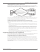
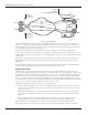


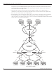


Table Of Contents
- Introduction
- Scope
- Design Considerations—Connectivity at the Branch Office
- Branch-Office Connectivity over IPsec VPN
- Design Recommendations
- Routing Information Protocol
- Traffic Load Balancing for Type B and Type C Branch Deployments
- Using Border Gateway Protocol for Large Networks
- Using OSPF for Small Number of Branch Offices
- Using Auto Connect VPN to Create Branch-to-Branch IPsec Tunnels
- High Availability for the Branch Office
- High Availability Requirement Levels (Link, Device, Device, and Link Levels)
- High Availability Functionalities
- High Availability for Branch Office Type A
- VPN Security Zone Configuration for Type A
- High Availability for Branch Office Type B
- Using Secure Services Gateway for Type B
- High Availabilty for Branch Office Type C
- Connectivity at the Data Center
- Implementing a High Availability Enterprise Network at the Data Center
- Quality of Service Design Requirements
- WX Design Requirements
- Summary
- Appendix A Related Documents
- Appendix B Naming Conventions
- Appendix C Products
- About Juniper Networks
- Figure 1: Connecting branch offices, campus locations, and data centers over a single converged network
- Figure 2: Branch office reference architecture
- Figure 3: Multi-tiered/layered network architecture
- Figure 4: Two-tier network design for data centers
- Figure 5: Branch with dual internet connections (load balancing using ECMP)
- Figure 6: BGP routing design
- Figure 7: Star topology – connecting branches to central hub
- Figure 8: AC VPN provisioned tunnels between branches in the same region
- Figure 9: Multi-tier topology
- Figure 10: HA configuration for Type A
- Figure 11: VPN security zone configuration for Type A
- Figure 12: Type B optimized – HA configuration
- Figure 13: Type B – security zones
- Figure 14: Type C – HA configuration
- Figure 15: Intra-branch using OSPF
- Figure 16: Branch Type C – security zones
- Figure 17: Enterprise network for the data center
- Figure 18: M Series Multiservice Edge Routers
- Figure 19: Internet firewalls
- Figure 20: VPN firewalls
- Figure 21: VPN firewall IPS policy
- Figure 2: Branch office reference architecture
8 Copyright © 2010, Juniper Networks, Inc.
APPLICATION NOTE - Branch Office Connectivity Guide
Figure 6: BGP routing design
The main advantages of this design are that it accommodates multiple devices and scales to a large number of
remote offices. Route processing is somewhat distributed by route reflectors. However, each device still has to go
through the BGP route selection process, but the number of sessions that each firewall has to maintain is minimal—
as is the number of messages that it has to process.
Unfortunately, while ubiquitous on service provider environments, BGP is not commonly used by enterprise
customers. This lack of expertise can prove to be challenging as the administration of the network becomes more
complex. Also, the extra cost of the equipment—when employing route reflectors—must be weighed when selecting
a final design.
Typically, when service providers sell the large-scale IPsec VPN service to their customers, they use BGP as the
routing protocol in a similar manner. This solution is well tested and has been shown to work in large customer
deployments.
Also, BGP might be a good choice as an interior gateway protocol (IGP) inside each data center (and between data
centers). For information about using this protocol, see the Internet Connectivity section.
Using Static Routes
A simple solution used for connectivity consists of using static routes at both endpoints of the tunnel. On each
branch, a single aggregate route for the entire internal network (and a more specific route pointing to the data center
terminating the tunnel) is configured. In turn, at the data center, a route for each remote network is configured by
mapping traffic to the particular tunnel. By modifying the metrics for the routes on both endpoints of each backup
tunnel, traffic is directed to the backup tunnels only during a failure. An IGP routing—for example, OSPF—can then
be used to distribute the static routes configured at each VPN concentrator. For additional information about the data
center IGPs, see the Internet Connectivity and the Internet Connections sections.
Although basic to deploy, using static routes has several disadvantages:
• Provisioning and managing the routes can become troublesome particularly because each site can have from
one to four tunnels. A minimum of 3,000 static routes must be configured (one on the data center for each site,
and two at each site).
• Modifying the addressing space at a branch requires manual reconfiguration. The firewalls at the head-end
of the network, terminating the IPsec tunnels, require reconfiguration with static routes pointing to the new
addresses.
• Relying completely on an external form of dead peer detection (DPD)—such as IPsec DPD, Internet Key
Exchange (IKE) keepalives, or VPN monitoring—is desired so traffic can be switched during a failure.
With this design, traffic originating at a device directly connected to a VPN concentrator and terminating a
backup tunnel cannot reach the remote office associated with that tunnel. The problem resides on the protocol
DATA CENTER 2
DATA CENTER 1
CE 1
CE N
RR1
RR2
OSPF
AREA 0
IBGP
IBGP
IBGP
IBGP
IBGP
IBGP
IBGP
Advertises
DC 1 Network
DC1 + DC2 Aggregate Network
Advertises
CE 1 Network
Local Pref 200
Advertises
CE N Network
Local Pref 100