
manual
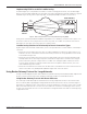
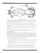


Table Of Contents
- Introduction
- Scope
- Design Considerations—Connectivity at the Branch Office
- Branch-Office Connectivity over IPsec VPN
- Design Recommendations
- Routing Information Protocol
- Traffic Load Balancing for Type B and Type C Branch Deployments
- Using Border Gateway Protocol for Large Networks
- Using OSPF for Small Number of Branch Offices
- Using Auto Connect VPN to Create Branch-to-Branch IPsec Tunnels
- High Availability for the Branch Office
- High Availability Requirement Levels (Link, Device, Device, and Link Levels)
- High Availability Functionalities
- High Availability for Branch Office Type A
- VPN Security Zone Configuration for Type A
- High Availability for Branch Office Type B
- Using Secure Services Gateway for Type B
- High Availabilty for Branch Office Type C
- Connectivity at the Data Center
- Implementing a High Availability Enterprise Network at the Data Center
- Quality of Service Design Requirements
- WX Design Requirements
- Summary
- Appendix A Related Documents
- Appendix B Naming Conventions
- Appendix C Products
- About Juniper Networks
- Figure 1: Connecting branch offices, campus locations, and data centers over a single converged network
- Figure 2: Branch office reference architecture
- Figure 3: Multi-tiered/layered network architecture
- Figure 4: Two-tier network design for data centers
- Figure 5: Branch with dual internet connections (load balancing using ECMP)
- Figure 6: BGP routing design
- Figure 7: Star topology – connecting branches to central hub
- Figure 8: AC VPN provisioned tunnels between branches in the same region
- Figure 9: Multi-tier topology
- Figure 10: HA configuration for Type A
- Figure 11: VPN security zone configuration for Type A
- Figure 12: Type B optimized – HA configuration
- Figure 13: Type B – security zones
- Figure 14: Type C – HA configuration
- Figure 15: Intra-branch using OSPF
- Figure 16: Branch Type C – security zones
- Figure 17: Enterprise network for the data center
- Figure 18: M Series Multiservice Edge Routers
- Figure 19: Internet firewalls
- Figure 20: VPN firewalls
- Figure 21: VPN firewall IPS policy
- Figure 2: Branch office reference architecture
Copyright © 2010, Juniper Networks, Inc. 7
APPLICATION NOTE - Branch Office Connectivity Guide
Implementing ECMP as an Aid in Load Balancing
As shown in Figure 5, it is still possible to use both access links. Creating a pair of tunnels, each routed through a
different connection (both originating on the same data center and terminating on the branch), provides the required
load balancing. In this way, traffic is split using equal-cost multipath (ECMP) across both access interfaces.
Figure 5: Branch with dual internet connections (load balancing using ECMP)
Finally, for the solution to provide both load balancing and data center redundancy, each branch office requires a set
of four IPsec tunnels. As a rule, only two of these tunnels carry traffic to each data center, while the other two are
dedicated to one of the data centers that experiences complete failure.
Load-Balancing Solutions in Relationship to Branch Connection Types
By observing the aforementioned considerations, there are three possible tunnel scenarios and their relationship to
connection:
• Branch Offices with a Single Connection: These are single-homed branches that have a unique tunnel to each
head office. Because each head office has two Internet links, the tunnels are evenly split between these two for
a total of 500 tunnels per link.
• Branch Offices with a Single Connection to the Internet and a Single Connection to a Private Network (or PTP
network): Branch offices connecting to the private network have a single tunnel to each data center using the
private network. They also have a single tunnel to each data center through the public network. The tunnels
across the private network are always preferred to those that use the public network. Therefore, there is no
traffic load balancing in this scenario.
• Branch Offices with Dual Internet Connections: For branch offices with dual Internet connections that have two
tunnels to each data center, ECMP provides load balancing for traffic across the tunnels.
Using Border Gateway Protocol for Large Networks
For large network deployments (more than 1,000 branches), Border Gateway Protocol (BGP) should be implemented
because it is better suited to control route instabilities and a large number of network advertisements.
Using Border Gateway Protocol with Route Reflectors
The last design considered attempts to off-load most of the routing computations to a device other than the VPN
devices. To do this, BGP helps propagate routing information with the aid of a route reflector, as shown in Figure 6.
Branch devices establish their IPsec tunnels with the central (or regional) offices. Each IPsec tunnel carries a single
BGP session from the branch office to a route reflector located in the central office terminating the tunnel. In turn,
the route reflector performs the route selection and sends the routing information to the VPN concentrator by using
a single BGP session.
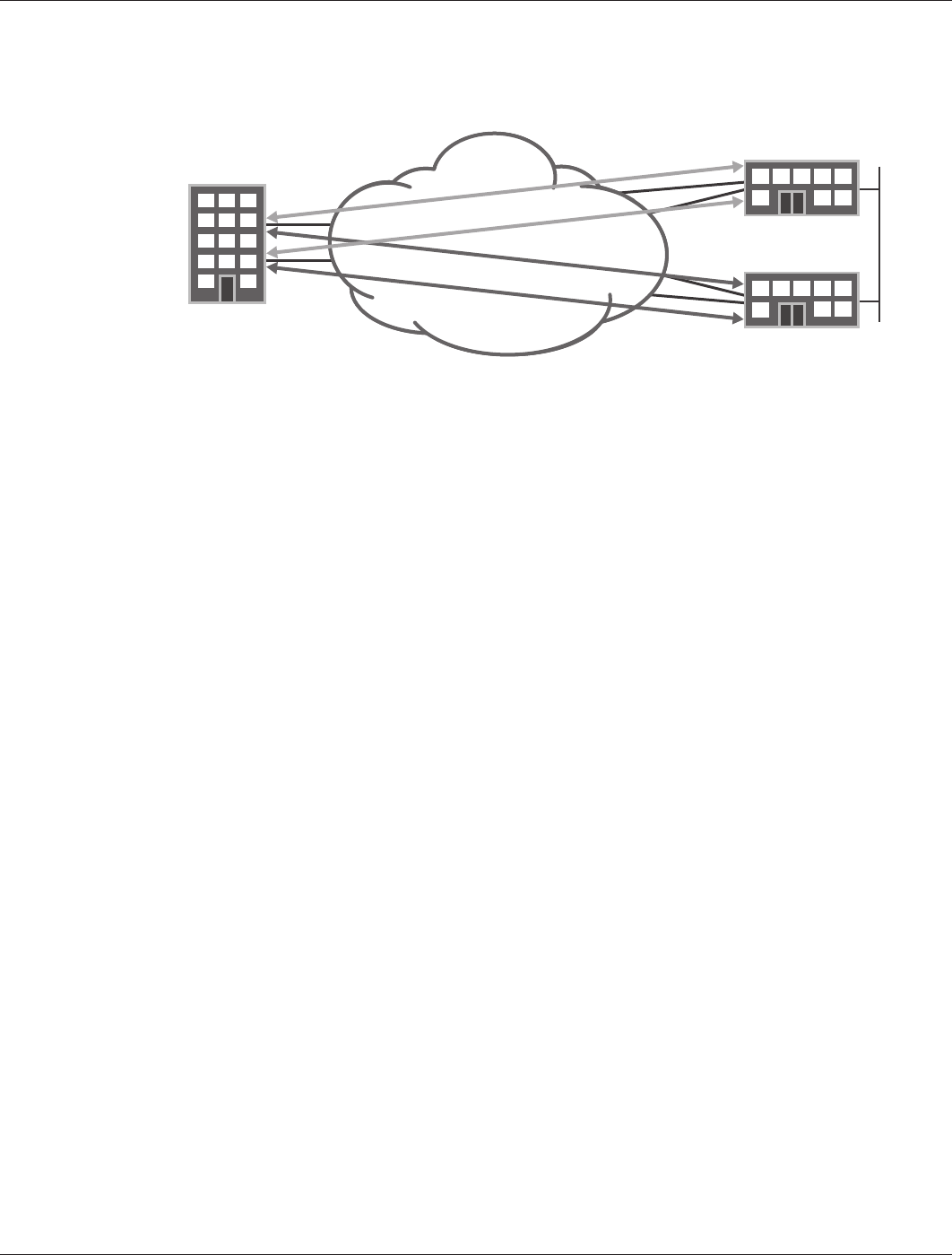
BRANCH
OFFICE
DATA CENTER 2
DATA CENTER 1
IPsec
Tunnel
IPsec
Tunnel
IPsec
Tunnel
IPsec
Tunnel
L2 Connection