
User Manual


•
You can install any transceiver supported by the DPC. For information about installing and
removing transceivers, see the hardware guide for your router.
•
Fiber-optic small form-factor pluggable (SFP) transceivers:
•
Connector: Duplex LC/PC (Rx and Tx)
•
1000BASE-EX (model number: SFP-GE40KM)
•
1000BASE-LH (model number: SFP-1GE-LH)
•
1000BASE-LX (model number: SFP-1GE-LX)
•
1000BASE-SX (model number: SFP-1GE-SX)
Optical interface specifications—see Gigabit Ethernet 1000BASE Optical Interface Specifications
•
Copper SFP transceivers:
•
Connector: Four-pair, Category 5 shielded twisted-pair connectivity through an RJ-45
connector
•
1000BASE-T (model number: SFP-1GE-T)
•
Pinout: MDI crossover
•
Length: 328 ft/100 m
Copper interface specifications—see Gigabit Ethernet 1000BASE-T Copper Interface
Specifications
•
Bidirectional SFP transceivers:
•
Connector: Duplex LC/PC (Rx and Tx)
•
1000BASE-BX (model number pairs: SFP-GE10KT13R14 with SFP-GE10KT14R13,
SFP-GE10KT13R15 with SFP-GE10KT15R13, SFP-GE40KT13R15 with SFP-GE40KT15R13)
Optical interface specifications—see Fast Ethernet and Gigabit Ethernet Bidirectional SFP
Optical Interface Specifications
NOTE: Do not install Gigabit Ethernet SFPs in the SONET/SDH port. The port will not recognize
the SFP.
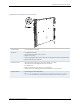
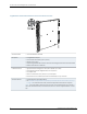
Cables and connectors
OK/FAIL LED, one bicolor:
•
Steady green—DPC is functioning normally.
•
Blinking green—DPC is transitioning online or offline.
•
Red—DPC has failed.
Link LED, one green per port:
•
Off—No link.
•
On steadily—Link is active.
The Link LEDs are labeled in groups of five:
•
0/0 for 0/0 through 0/4
•
0/5 for 0/5 through 0/9
•
1/0 for 1/0 through 1/4
•
1/5 for 1/5 through 1/9
•
2/0 for 2/0 through 2/4
•
2/5 for 2/5 through 2/9
•
3/0 for 3/0 through 3/4
•
3/5 for 3/5 through 3/9
LEDs
Related
Documentation
MX Series DPC Overview on page 4•
• DPCs Supported on MX240, MX480, and MX960 Routers on page 6
15Copyright © 2013, Juniper Networks, Inc.
Gigabit Ethernet Enhanced Ethernet Services DPC with SFP