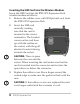
RTK GPS Expansion Pack Overview The RTK GPS Expansion Pack for the Carlson Surveyor+ and the Juniper Systems TK6000 handheld incorporates a high accuracy NovAtel RTK GPS receiver and an EDGE class wireless modem (GSM). This combination enables precision measurements to be made with a small, lightweight handheld device. The NovAtel RTK GPS receiver incorporates state-of-the-art positioning technology using GPS and GLONASS dual frequency receivers, which feature NovAtel’s AdVance RTK and ALIGN technologies.
The GPS receiver uses COM port 7 and COM port 8 with a default of 9600 baud, 8 data, no parity, 1 stop bit. GPS Antenna For the GPS antenna, we recommend using the Novatel dual frequency, dual constellation antenna model 702-GG. Wireless Modem Operation The following steps are required to get the GSM modem ready to use (these steps are described in this manual): ! Set up a wireless service data account for the GSM modem and receive a SIM (Subscriber Identification Module) card.
GSM Account Set Up and Activation Process Follow these steps to set up a wireless account for the data modem: 1. Contact your wireless provider to obtain an account and SIM card. Since you already have the equipment, and all you need is to set up an account, it is best to work directly with the wireless provider, i.e.; AT&T, T-Mobile, Vodafone, etc. 2. When you contact the wireless provider, inform them that you have a wireless data modem and need to set up data service for this device.
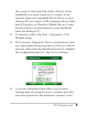
• 4. The modem’s 15-character IMEI number: This is shown on the Cell Modem Setup screen shown below: You may be asked for the modem’s model number. This number allows the carrier to verify this modem has been approved for use on their network. The internal modem module is a MultiTech model MTSMC-E1. IMPORTANT: Do not confuse this number with the model number of the handheld computer which is not needed by the carrier.
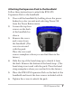
Inserting the SIM Card into the Wireless Modem Insert the SIM Card into the RTK GPS Expansion Pack wireless modem as follows: 1. Remove the rubber cover with SIM printed on it from the RTK GPS Expansion Pack. 2. ! Insert the SIM card carefully, making sure that the card is inserted in the correct orientation. The beveled corner on the card lines up with the outline on the socket, with the gold electrical contacts facing towards the socket. CAUTION: There is space between the case and the socket.
Attaching the Expansion Pack to the Handheld Follow these instructions to attach the RTK GPS Expansion Pack to the handheld: 1. Power off the handheld by holding down the power button for a few seconds and selecting Power Off from the Power Button menu. 2. Loosen the top four screws on the back of the handheld as shown. 3. Remove the cover and screws from the handheld. (The cover is not used with the pack. Place the cover and screws someplace where you can find them in the future.) 4.
Attaching the Antennas to the Expansion Pack Follow these instructions to attach the antennas to the RTK GPS Expansion Pack: 1. Attach the GSM modem antenna North American or International) to the RTK GPS expansion pack. The GSM modem antenna connector is the smaller of the two coaxial connectors (SMA) on the top of the pack. Use the knurled ring at the bottom of the antenna to tighten the antenna. Do not twist on the antenna rod to tighten the antenna.
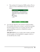
the screen to download the utility directly to the handheld (you need a method to connect to the internet from your handheld like Wi-Fi) or to your desktop PC (you need a USB communications cable and ActiveSync or Windows Mobile Device Center for the utility to be transferred to your handheld from the desktop PC). 2. To start the utility, Tap Start > Programs > Cell Modem Setup. 3. This screen is displayed.
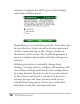
internet. Configure the APN (Access Point Name), username, and password. Depending on your wireless provider, there may only be one selection. Select one of the choices presented on this screen and tap on the Configure button at the bottom of the screen. The handheld performs a reset to configure the modem with the settings you selected. Wireless providers occasionally change these settings.
It is best to get this information (APN, username, and password) directly from your wireless provider when you subscribe and enter it manually as outlined in the next step. 5. If the only selection in the list is “Other”, you must obtain that information (APN, user name, and password) from the wireless provider and manually enter this information. Select “Other” on the list and then tap on the Configure button at the bottom of the screen.
If you cannot determine the correct settings, leave all the fields blank and select OK. In many instances this work. View Current Settings To view current settings, launch the Cell Modem Setup utility and tap on the Menu button at the bottom of the screen. Select the About menu item. A screen showing the current settings is shown.
GSM Modem Operation The following icons may be displayed on the status bar at the top of the screen. They indicate various states related to the operation of the wireless modem in the expansion pack: No SIM Card—This icon notifies the user that: a) no SIM card is installed and b) it will be impossible to create an internet connection using the cell modem until a valid SIM card is installed.
The quality of the wireless modem signal and the data transmission speed is dependent on the signal strength displayed. 0 bars: There is not a reliable signal. Don’t attempt to send data. If no bars are displayed it may be necessary to move to another location with better signal strength in order to send and receive data effectively. 1 bar: Signal strength is weak and the data transmission speed will be slow. 2–4 bars: Signal strength is strong and transmission speed will be faster.
The IMSI number is an indication from the SIM card. It is unique to each card. Configuration is not possible if the SIM card is not detected. If a SIM card has been installed and there is still an error a new SIM card may be required. You can obtain a new SIM card from your wireless provider. Sending AT Commands This screen is used for troubleshooting by a qualified technician. There is no need to use it unless directed by a service technician.
To send AT commands directly to the modem, tap Menu > Commands to view this screen: The current port is displayed along with the current baud rate. In this example, the GSM modem has not yet been configured. Port: is “COM5.” When it is configured, Port: will be “VCA1.” Type commands in the command box and press Enter to send commands directly to the modem. Responses are displayed in the box above the command box. This may be useful for diagnosing problems.
Uninstall/Deactivate RTK GPS Expansion Pack When removing the expansion pack from the handheld, you should go through this procedure to de-activate the pack, and remove all configuration settings for the pack. 1. To uninstall the RTK GPS Expansion Pack, launch the Cell Modem Setup utility and tap Menu, then Remove Configuration. 2. The modem configurations will be removed from the handheld. During the process the handheld performs a reset to complete this process 3.
! Wireless Safety CAUTION: Maintain a separation distance of at least 20 cm (8 inches) between the transmitter’s antenna and the body of the user and nearby persons. RF Interference Issues It is important to follow any special regulations regarding the use of radio equipment due in particular to the possibility of radio frequency, RF, interference. Please follow the safety advice given below carefully. Switch OFF your cell modem when in an aircraft.
Operation of your cell modem close to other electronic equipment may also cause interference if the equipment is inadequately protected. Observe any warning signs and manufacturers’ recommendations. Maintenance of Your RTK GPS Expansion Pack Your expansion pack is the product of advanced engineering, design, and craftsmanship and should be treated with care. The suggestions below will help you to enjoy this product for many years. Do not attempt to disassemble the expansion pack.
FCC Rules. Operation of this equipment is subject to the following two conditions: 1. The device may not cause harmful interference. 2. This device must accept any interference received, including interference that may cause undesired operation. In compliance with the FCC rules, 47 CFR 15.105(b), the user must be notified that this equipment has been tested and found to comply with the limits for a Class B digital device, pursuant to part 15 of the FCC Rules.
Connect the equipment into an outlet on a circuit different from that to which the receiver is connected. Consult the dealer or an experienced radio/TV technician for help. In compliance with the FCC rules, 47 CFR 15.21, the user must be notified that changes or modifications to the Field PC that are not expressly approved by the manufacturer could void the user’s authority to operate the equipment. Only approved accessories may be used with this equipment.
There cannot be any alteration to the authorized antenna system. The antenna shipped with the GSM modem is the only one authorized for use. An antenna must be used when the pack is on the device. Using the wrong antenna or using the pack without an antenna voids the warranty. This wireless modem is compliant with FCC regulations when operated within the temperature range of -20°C to +54°C. Do not operate the wireless modem outside of this temperature range.
ETSI EN 301 489-1, -7, EMC for Radio Equipment ETSI EN 301 511 GSM ETSI EN 300 440 GPS The telecommunication functions of this device may be used in the following EU and EFTA countries: Austria, Belgium, Bulgaria, Cyprus, Czech Republic, Denmark, Estonia, Finland, France, Germany, Greece, Hungary, Iceland, Ireland, Italy, Latvia, Liechtenstein, Lithuania, Luxembourg, Malta, Netherlands, Norway, Poland, Portugal, Slovak Republic, Romania, Slovenia, Spain, Sweden, Switzerland, and United Kingdom.
Specifications GPS Receiver Manfacturer: Novatel Channel Configuration 14 GPS L1, 14 GPS L2 12 GLONASS L1, 12 GLONASS L2 2 SBAS Horizontal Position Accuracy (RMS) Single Point L1 1.5 m Single Point L1/L2 1.2 m SBAS2 0.6 m DGPS 0.4 m RT-203 0.2 m RT-2 1 cm+1 ppm Measurement Precision (RMS) GPS GLO L1 C/A Code 4 cm 15 cm L1 Carrier Phase 0.5 mm 1.5 mm L2 P(Y) Code 8 cm L2 Carrier Phase 1 mm 1.