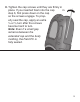
Installation Instructions Ultra-Rugged Field PC Extended Caps Our extended caps maintain the full ruggedness of the Field PC while allowing you to use CF or SD peripheral devices. This booklet explains how to install each cap and also how to mount an external device like a GPS receiver to your Field PC. Before You Begin • Maximum card lengths for each cap are listed on page 3. To avoid damaging your Field PC, refer to them before inserting a card.
Package Contents Communication Cap: • Foam pads in different sizes Universal and Optical Caps: • Foam pads in different sizes • Seal adapter plate and screws • Card pull tabs • Clear CF card spacer Required Tools • #1 Phillips screwdriver • If you are mounting an external device, you need a razor blade or sharp knife 2
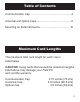
Table of Contents Communication Cap........................................................ 4 Universal and Optical Caps................................................ 6 Mounting an External Device......................................... 10 Maximum Card Lengths The maximum total card length for each cap is listed below. CAUTION: Using cards that exceed the maximum lengths listed above may damage your Field PC and void the warranty. Communication Cap Universal Cap Optical Cap 2.75 inches (70 mm) 3.
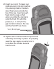
Communication Cap This section explains how to install the Communication Cap. For instructions on installing the Universal and Optical caps, see the next section. 1. Use a #1 Phillips screwdriver to loosen the captured top screws on the Field PC. Remove the standard cap.
2. Insert your card. To keep your card securely in its slot, cushion it by placing small or mediumsized foam pieces inside the top of the cap. Insert enough foam into the cap so that when you slide the cap back onto the Field PC with little pressure, a ¼ inch (6 mm) gap remains between the cap and the Field PC as shown. ¼ in. (6 mm) gap 3. Tighten the Communication Cap screws until they are firmly in place. To properly seal the cap, apply an extra ¼ to ½ turn after the screws become hard to turn.
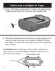
Universal and Optical Caps 1. Use a #1 Phillips screwdriver to loosen the captured top screws on the Field PC. Remove the standard cap. 2. This section tells you how to insert your card(s) properly. For memory cards, see step 3. For medium or large CF cards, see step 4. For any other card types, insert your card(s) and skip to step 5. CAUTION: Before inserting a card, make sure the four side screws on the seal adapter plate are backed out 1/8 inch as shown below.
3. If you are inserting an SD or CF memory card, make it easier to remove by first placing a card pull tab onto the card. 4. There are two types of CF cards: Type 1 and Type 2. A Type 1 card is thinner than a Type 2, and requires the use of a spacer. To insert a Type 1 card, hold the spacer (shown below) to the front of the card while you insert the card into the rear slot of the adapter. Type I CF card spacer 5.
6. Once you have inserted your card(s), hold it in place while you tighten the adapter plate screws. Then tighten the four small side screws until the top of each screw is flush with the outside of the gasket piece. CAUTION: Before removing an inserted card, loosen the four small side Adapter screws by 1/8 inch (3 mm). Plate screws 7. The kit includes large- and medium-sized foam pieces. Insert foam pieces inside the top of the cap to keep the device in place.
8. Tighten the cap screws until they are firmly in place. If you inserted foam into the cap in step 6, first press down on the cap so the screws engage. To properly seal the cap, apply an extra ¼ or ½ turn after the screws become hard to turn. Note: Even if a small gap remains between the extended cap and the body molding, the Field PC is fully sealed.
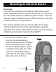
Mounting an External Device Overview The Field PC features a convenient cable channel that hides cables attached to an external device you mount on the Universal, Optical, or Data Acquisition Caps. External devices might include an external RS-232 sensor (such as a GPS receiver) or a USB device. This section explains how to insert a cable in the cable channel and how to mount the external device onto the extended cap. These instructions assume you have already installed your extended cap onto the Field PC.
2. Thread the sensor cable along the cable channel and out through the body molding. 3. With the cable in place, slide the body molding into place and tighten the four side screws. Replace the battery pack, battery door, and hand strap.
4. Connect the sensor connector to the 9-pin serial port or USB host port. 5. Make sure the seal adapter plate is properly installed. CAUTION: The seal adapter plate must be installed to seal the Field PC. If you have not already installed the seal adapter plate onto your Field PC, see steps 2–4 of the previous section for instructions.
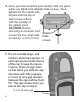
6. To give the cable an exit through the extended cap, cut the thin rubber overmolding on the extended cap along the entire scribe line using a razor blade or sharp knife. make cut here 7. Slide the extended cap onto the Field PC and push the sensor cable through the incision you made so that the cable exits out of the top of the cable channel. Note: The incision does not affect the seal of the Field PC.
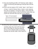
8. Tighten the cap screws until they are firmly in place. To properly seal the cap, apply an extra ¼ to ½ turn after the screws become hard to turn. 9. Mount the sensor on the front of the extended cap and secure it with a strap. Note: An optional sensor mounting strap is available for purchase. The figure here shows a GPS antenna mounted on the Universal Cap and secured with the sensor mounting strap.
Selection Chart UN Wi-Fi X X X Cellular Modem X X X Bluetooth (Class 1 or 2) X IV CO M M UN IC ER ATIO SA N OP L TI CA L CF & SDIO cards X X Digital Camera X X GPS Receiver X Bar Code Scanner X RFID Scanner X X NI CF-6004 CF Memory Card X X X SDIO Memory Card X X X P/N 15147-02 © Copyright 05/11. Juniper Systems, Inc. All rights reserved. Information subject to change without notice.