User’s Manual © Copyright 2004 Juniper Systems, Inc. ® Juniper Systems, Inc. and LandMark CE User’s Manual 1 Allegro Field PC are registered trademarks; TM LandMark CE and Allegro CX are recognized trademarks of Juniper Systems, Inc.
Part number: 14653-01 Release Date: August 2005 Editor: R.
Table of Contents Chapter 1 Introduction....................................................... 5 Welcome...................................................................................6 Features ...................................................................................7 Software License Agreement ...................................................8 Chapter 2 Installation......................................................... 9 First Time LandMark CE Installation ............................
LandMark CE User’s Manual
Chapter 1 Introduction Welcome Features Software License Agreement LandMark CE User’s Manual 5
Welcome We would like to welcome you as a user of LandMark CE, a GPS Receiver Utility™ software program. LandMark CE is designed to serve as the interface between a GPS receiver connected to an Allegro Field PC, and an application program. Recognizing the need of custom and third party application software for real-time GPS data streams, Juniper Systems has developed this utility program to manage the GPS receiver connectivity functions.
Features Connects with a wide variety of GPS receivers using the NMEA data streams. Multiple data interfaces to other programs running concurrently. Shared memory, data exchange file, and wedging your GPS data into other programs using a Hot Key are options for data interface. Sky plot and satellite signal strength bars keep you informed of GPS status and quality. Navigation screen allows you to select To and From waypoints.
Software License Agreement ▲ Manufacturer Agreement This Software License Agreement is between the end-user and the manufacturer (Juniper Systems, Inc.) Please read the following terms and conditions before using LandMark CE for use with the Allegro. This agreement supersedes any prior agreement, written or oral. Granting of License The manufacturer grants, under the following terms and conditions, a non-exclusive license to use the LandMark CE software. Ownership Juniper Systems, Inc.
Chapter 2 Installation First Time LandMark CE Installation Additional LandMark CE Installations Uninstalling LandMark CE LandMark CE User’s Manual 9
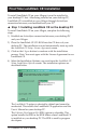
First Time LandMark CE Installation To install LandMark CE on your Allegro it must be installed to your desktop PC first. After being installed on your desktop PC, LandMark CE is installed on your Allegro through ActiveSync connection between your handheld and your PC. ▲ Step 1: Installing LandMark CE on the desktop PC To install LandMark CE on your Allegro, complete the following steps: 1) Establish an ActiveSync connection between your desktop PC and your Allegro.
The Start Menu Shortcuts option is a selectable. This option places a LandMark CE folder located in the Programs folder of your Start Menu. Inside the LandMark CE folder is the Land Mark CE Uninstall program and the LandMark CE User’s Manual, which is a .pdf file. Note: Acrobat Reader is required to open the User’s Manual .pdf. 5) Select the location on your desktop PC that you want LandMark CE installed.
After LandMark CE is installed on your desktop PC, the following message appears if the Allegro is connected to the desktop PC through ActiveSync: Clicking on the Yes button continues the installation of LandMark CE onto your Allegro to the default application install directory. The default folder is C_Drive\Program Files. Note: We recommend that you click on the Yes button and install LandMark CE to the default application install directory.
After a install destination is confirmed, the following message box pops up: This screen directs you to finish the installation on the Allegro. Click on OK and proceed to Step 2: Installing LandMark CE on the Allegro to complete the installation. If the Allegro is not connected to the desktop PC through ActiveSync, the following message box appears: This screen indicates that the next time your Allegro connects to the desktop PC that the installation of LandMark CE to the Allegro will be completed.
When the following screen appears on your desktop PC, an install progression bar appears in a window on the screen of your Allegro. After the installation of LandMark CE is completed on your Allegro, the Registration screen appears. LandMark CE Registration Screen LandMark CE is a licensed application and requires a Serial Number and Registration Key to completely activate the program. Name The Name box is used to identify who purchased the program. This can be either an individual or a company name.
Save System After you have installed LandMark CE on your Allegro, we recommend that you perform a Save System utility on your Allegro. To save the system on your Allegro, complete the following steps: 1) Tap on Start | Programs | Utilities | Save System. 2) Wait for the registry on your Allegro to save and for Save System screen to close.
Additional LandMark CE Installations Once LandMark CE has been installed on your desktop PC it does not need to be reinstalled each time you want to install LandMark CE on additional Allegro’s. You will need a seperate Serial Number and Registration Key for each copy of LandMark CE you put on each Allegro.
3) Select the Juniper System LandMarkCE option so a checkmark appears next to option. 4) Click on the OK button to proceed with the installation. After a install destination is confirmed, the following message box pops up: This screen directs you to finish the installation on the Allegro. 5) Click on OK and proceed to Step 2: Installing LandMark CE on the Allegro to complete the installation.
Uninstalling LandMark CE Since LandMark CE is installed on the desktop PC and the Allegro, the process for uninstalling the application varies depending on which device you are uninstalling LandMark from. The following sets of instructions are device specific, use the one that address your your uninstall request.
Chapter 3 Using LandMark CE Introduction and Operation GPS Status Screen Navigation Screen Configuration Screen Waypoint Screen LandMark CE User’s Manual 19
Introduction and Operation After LandMark CE is installed, you can operate it in the field or office. This chapter describes the operation, screens, and specific features of the program. To begin using LandMark CE, double-tap on the LandMark CE desktop icon. A splash screen displaying LandMark CE A GPS Receiver Utility and the version number are displayed for two seconds.
▲ Keyboard Options To navigate through LandMark CE, use a stylus and tap on the screen, or press the following keys on the Allegro: Key Open Screen F1 GPS Screen F2 Navigation Screen F3 Configuration Screen F4 Waypoint Screen F10 COM Port Connect/Disconnect Navigate within each screen by using the circular arrow key located in the center of the keyboard. Use the Tab key for cursor movement between fields. When you are in the desired field, press Enter to select whatever you have highlighted.
Open The Open option allows you to open an existing waypoint file. Convert Waypt File The Convert Waypt File allows you to convert a waypoint file into a data file. It may be necessary to convert a waypoint file for viewing in a different application. We recommend that if you need to convert a waypoint file that you do so only after the waypoint file is completed and all necessary data is collected. GPS Connect The GPS Connect option is only available when using Bluetooth with your GPS receiver.
About The About option opens a pop-up screen that displays the LandMark CE version number and date the version was completed. GPS Tapping on the GPS option opens the GPS screen. Nav Tapping on the Nav option opens the Navigation screen. Config Tapping on the Config option opens the Configuration screen. Way Pts Tapping on the Way Pts option opens the Waypoint screen. Mark Point Tapping on the Mark Point option opens the Mark Point screen.
GPS Status Screen The GPS status screen displays a skyplot that shows the position of each satellite transmitting GPS data. This screen also helps you determine how accurate the GPS readings are. To display the GPS Screen, complete one of the following steps: Tap on the GPS option at the top of the menu bar. Tap on Go to access a drop-down menu and select GPS. Press F1 on the Allegro keyboard.
When a satellite rises above the horizon, the GPS receiver can then receive a positioning signal from the satellite. The satellite then appears in the skyplot section of the GPS screen. GPS readings are more accurate when the satellites are more scattered across the sky. The right side of the screen displays a bar graph showing the relative satellite signal strengths. Each satellite is assigned an SV number (space vehicle or satellite vehicle number).
Note: The EHE reading appears in either feet or meters depending on the measurement preferences that are set in the Configuration screen. ▲ Elev Elev (elevation) is the altitude where you are geographically positioned. For display options, go to the Altitude Reference section later in this chapter.
Using 3D RTK or 2D RTK Mode The 3D RTK or 2D RTK mode is only displayed when the receiver being used is capable of reading RTK code from three or more satellites. ▲ GPS Status Quality — Not Receiving Data GPS status quality is shown to the right of Elev reading and consists of the following indicators when not receiving any data: No Com Actv. No New Data COM Discnt COM Errors No Fix No Com Actv. No Com Actv.
▲ Diagnostics Tap on the Diag (Diagnostics) button within the GPS Status screen. The GPS Diagnostics screen displays a dialog box showing your position and packet information, or NMEA data strings, supplied from GPS receiver. These NMEA data strings are displayed in their entirety and can be viewed by using the scroll bar at the bottom of the screen.
4 = RTK (Real-Time Kinematic) 5 = RTK (Real-Time Kinematic) 2D/3D The 2D/3D heading shows the current number of satilite fixes. 1 = no fix 2 = 2D fix (minimum of 3 satelites) 3 = 3D fix (minimun of 4 satelites) W1/W2 The W1/W2 heading shows WAAS satelites. 0 = no WAAS 1 = WAAS satellites visible but not used 2 = WAAS satellites used 3 = Visible and used Note: WAAS enabled receivers receive WAAS corrections, but not additional satellite information.
Sat # Sat #, or SV number, indicates the satellite vehicle, or space vehicle number. Azimuth Azimuth is the bearing measurement in degrees from North that represents the horizontal direction of the satellite from the current position. Elevation Elevation is shown in degrees and is the angular measurement above the Azimuth line, which gives the satellite’s height above the horizon. A satellite located lower on the horizon has a lower elevation in degrees.
Nav Screen The Nav screen allows users to collect point information, calculate point differences, check survey lines, and specify a path of travel. To display the Nav Screen, complete one of the following steps: Tap on the Nav option at the top of the menu bar. Tap on Go to access a drop-down menu and select Nav. Press F2 on the Allegro keyboard.
▲ To The To box displays the waypoint that is the ending point. This point is where you intend to stop at once you arrive there. Waypoint File Waypoint files are files consisting of points that have been saved and labeled. Before the navigation function can be used, a waypoint file must be identified and opened.
Distance The Distance box displays the distance in the selected current units (meters or feet) from the Here to the To location. Bearing The Bearing box displays the compass heading in degrees from Here to the To location. Track The Track box displays the direction you are traveling in degrees. Speed The Speed box displays the speed you are moving in current display units (km/h or mph).
▲ Heading Setting The heading setting is located below the Quality status line. It displays which heading the compass is set to. Options include True North, Auto Magnetic, Manual Magnetic, or the World Magnetic Model Epoch 2000 (WMM-2000 or WMM 2K). For more information about the heading settings and the options available to you, go to the Heading title in the Configuration Screen section of this chapter.
Configuration Screen The Configuration screen allows you to customize LandMark CE according to operational preferences. To display the Configuration screen, complete one of the following steps: Tap on the Cnf option at the top of the menu bar. Tap on Go to access a drop-down menu and select Config. Press F3 on the Allegro keyboard. Note: You must first exit the Configuration screen to be able to use the F1-F4 keys again.
▲ GPS Tab The GPS tab is used to configure the COM port you are using to attach the GPS receiver. Any changes to the communication port become effective immediately, a program restart is not needed. Port The Port field allows you to select the communication port you are using. LandMark CE currently supports communication ports COM1 through COM9. Note: If you are using the Holux receiver, you need to use COM1 and check the DTR option.
Bluetooth COM Ports LandMark CE has multiple automated functions specifically for Bluetooth receivers. Bluetooth COM Port Usage Auto Detection When a user selects a Bluetooth COM port or when the application loads, LandMark CE automatically detects when a Bluetooth COM Port is being used. If a Bluetooth receiver is set as a favorite when more than one device is available, loading the COM port defaults to the desired receiver and bypasses the Bluetooth device selection screen.
If using a GPSPOD with a Trimble Lassen LP receiver, complete the following steps, otherwise skip to step 6 and proceed: Note: Steps 1 - 5 only apply when using the built in GPS pod for the Allegro through COM 3. The Holux 211 receiver is completely external, or any Bluetooth, and only the settings in the Config screen need to be properly set. 1) Exit out of LandMark CE. 2) Tap on the Start button and navigate through Programs | Utilities | GPS Pod Setup.
Parity, Data Bits, Stop Bits As with Baud rate, the communication parameters for Parity, Data Bits, and Stop Bits must have those of the receiver. Parity, Data Bits, and Stop Bits are specified by the GPS receiver’s manual. Please see the user’s manual for these values and set them accurately. DTR The DTR (Data Terminal Ready) option uses a 5V power supply that is only used with COM1 and when a external GPS receiver is being used which needs a power supply.
When the Export button is tapped in the Mark Point screen, your last active application opens automatically. Press Enter or type a command to read the modified dtex.txt file and obtain the GPS data. (See the Mark Key section later in this chapter for further details on Mark Point screen.) Ini File Write Protected The Ini File Write Protected box indicates whether a general field user can change configuration settings when checked.
Each new position is included in the running average until the specified number of positions to calculate the overall average have been accumulated. Point Averaging is used when the Mark Point screen is open. Note: Masked position information is not included in the average. See the Mask Tab section in this chapter for more information. Number of Points Enter in a Number of Points after you have checked the Point Averaging box.
▲ Units Tab The Units tab is used to format data. For example, say that your data needs to be calculated in feet, with magnetic declination set, in UTM scale, and mean sea level altitude reference set. Set up all of these configurations in the Units tab. Selected settings are also used in displayed data for Keyboard Wedge and Memory Exchange. Datum The Datum option is a set of constants used for calculating coordinates on earth.
Units The Units option allows you to specify the units of measurement that you want your data to be expressed in. Choices include feet, miles, meters, kilometers, knots, miles per hour, or kilometers per hour. Display Option Distance Units Speed Units Statute Feet, Miles Miles per hour (mph) Metric Meters, Kilometers Kilometers per hour Nautical Feet, Nautical Miles Knots Feet Feet (changes to miles at 13,000 ft.
Manual Mag The Manual Mag value uses a negative (-) number for East declination and a positive (+) number for West declination. When manually entering the declination, use the box to the right of the Heading drop-down menu and specify either East (using a negative value) or West (using a positive value). WMM 2K Earth’s magnetic field, as measured by a magnetic sensor on or above the Earth’s surface, is a composite of several magnetic fields generated by a variety of sources.
Altitude Reference The Altitude Reference option displays the altitude as MSL (mean sea level) or HAE (height above ellipsoid). When MSL is selected, its value is calculated when the GPS receiver provides the geoidal separation value in the NMEA GGA packets from the satellite. ▲ Mask Tab The Mask tab is used to set the GPS signal masking parameters while marking waypoints. Only those GPS fixes that meet the specified criteria are used in averaging a waypoint.
DGPS Only Select the DGPS Only option to collect GPS fixes with differential corrections. When selected, all other points that are not DGPS are masked. 3D Only Select 3D Only to collect waypoints that are received when using at least four satellites. Min Sat Elevation Select Min Sat Elevation (Minimum Satellite Elevation) and specify the minimum elevation in the box to the left. Satellites that are equal to or greater than the elevation value entered are included in the waypoint averaging.
The following are the three keys that can be used for the Wedge Key or Mark Key: Task manager Insert Delete Mark Key Select a Mark Key from the drop-down menu. Whenever that key is pressed it brings up the Mark Point screen. Wedge Key Select a Wedge Key from the drop-down menu. Whenever that key is pressed, it sends the GPS position into another active application. See Keybd to specify the order you would like the data to appear.
Available Data Items Available Data Items are listed options for how and what data are transferred. Select data items by highlighting and then tapping the arrow button between the Available Data Items box and the Selected Data Items box. Available Data Items are then copied into the Selected Data Items box. Asterisks denote data that can be transferred, while items without asterisks specify data formatting options.
For example, when Tab is selected in Internal and ddd mm ss.ss is selected in Units/Format, a latitude data string in PTab is entered as follows: N has its own cell, ddd has its own cell, mm has its own cell, and ss.ss would have its own cell. This feature is nice for applications that require data calculations. Note: If you have an Internal option selected, be sure that your Selected Data Items box is filled in correctly.
Waypoint Screen Use the Waypoint screen to display and manage the contents of the currently selected waypoint file. The available functions allow for marking points, editing points, and deleting points from a waypoint file. To display the Waypoint screen, complete one of the following steps: Tap on the Wpt option at the top of the menu bar. Tap on Go to access a drop-down menu and select Way Pts. Press F4 on the Allegro keyboard.
When New is tapped, a pop-up screen appears. Change the Waypoint ID and fill in latitude, longitude, and elevation. The units format depends on what is selected in the configurations screen. (See Configuration instruction to change Units format.) Waypoint # Waypoint # is the number assigned by LandMark CE. All points in a waypoint file are numbered consecutively. Waypoint ID Waypoint ID is the point name that you give to a point. Latitude Latitude shows a waypoint latitude.
Note: A recommended practice is not to edit a waypoint very many times when using a datum other than WGS-84. The conversion between datums that occurs internally can potentially introduce errors into the original GPS data. ▲ Del (Delete) Tap Del to delete the selected waypoint. When the pop-up box appears, select yes to delete, or select no to return to the Waypoint screen. ▲ Mark Tap on the Mark button to capture a current location waypoint using the Mark Point pop-up screen.
Offset Tapping on the Offset button opens a Offset Input screen. This screen enables the user to specify the distance, direction, and slope from the initial (current) location to an offset location. Distance The Distance box sets the direct distance in displayed units to the offset point. Direction The Direction box sets the angle, in degrees, measured from North to the offset point. Next to the Direction box is the Ref (reference) label.
4) Check the Offset On check box, after these fields are filled in, if you want the offset calculations activated before closing the waypoint. Now, whenever you select the saved offset point, if the Offset On check box is checked, an indicator appears in the Waypoint screen while viewing the point information. If you want to view the unaltered point information, tap on the Edit button in the Waypoint screen.
Export The Export button starts the average function, and then exports the averaged point to your Waypoint Data Path (See Configuration/File to set up Waypoint Data Path). Note: When the waypoints file reaches the 256 point limit, the Export button can still be used to export data to another application, but a new waypoint file must be created if additional points must be stored. Cancel Tapping the Cancel button closes the Mark Point screen.
LandMark CE User’s Manual
Chapter 4 Troubleshooting Error Messages and Warnings LandMark CE User’s Manual 57
Error and Warning Messages LandMark CE displays pop-up messages when an error occurs. The following section lists the possible error messages and suggests how to fix the problems related to an error message. ▲ LandMark CE Startup Error Messages The following are the error messages and suggested fix for those messages that may occur during LandMark CE startup. Error message: Application Path Not Found. Please make sure the path ‘C_Drive\C_Program Files\LandMarkCE’ exists.
Error message: Could not find Ellipse.dat file. Ellipse.dat files are datum files saved in the registry. This error message appears for one of the following reasons: 1) The registry is corrupt, or a Set Factory Default was executed. 2) The program path was modified, so the registry path is no longer available. 3) The ellipse.dat files were deleted. To solve the problem, check the registry path. Registry errors can be fixed by doing a soft reset. If the soft reset does not work, reinstall LandMark CE.
Error message: Datum not defined. Using WGS84 (Default Datum). This message appears for the following reason: 1) A programmer changed the datum in the lm.ini file. The new datum value was not valid and is therefore unusable by LandMark CE. LandMark CE automatically defaults to WGS84 when this happens. Fix the error by changing the lm.ini file datum. See Programmers chapter for more information. Error message: Cannot open LandMark CE registry key.
Error message: . (Error Reading Application Path Value.) Every command in the registry comes in a key-value pair. When the key-value pair is not functioning correctly, LandMark CE cannot read the application path value. This problem could happen because of one of the following reasons: 1) A Set Factory Default was executed and erased the key-value. 2) The registry has been corrupted. Registry errors can be fixed by doing a soft reset. If the soft reset does not work, reinstall LandMark CE.
Error message: Directory does not exit. Using “\C_Drive\C_MyDocs\. When LandMark CE is closed, the current waypoint file is automatically saved and opened when the program is executed again. This message appears for the following reason: 1) You change the name of the file after closing LandMark CE.
Error message: Failed to open waypoint file and create the converted file. This error message appears for the following reason: 1) A waypoint file conversion fails at the beginning of the process because the waypoint file could not be accessed. Fix the error by doing either a soft reset or by deleting old files to free up disk space. Error message: Failed to create the converted file. This message pops-up when trying to either create a new converted file or write data to a new converted file.
Error message: Could not create shared memory. Method stopped. The error message appears for the following reason: 1) An error reserving shared memory has occurred. To fix the error do a soft reset and restart LandMark CE. ▲ LandMark CE Mark Point Screen Error Messages The following are the error messages and suggested fix for those messages that may occur when using the LandMark CE Mark Point screen. Error message: Waypoint name can be 30 characters or less. Characters after 30 will be truncated.
▲ LandMark CE Waypoint Screen Error Messages The following are the error messages and suggested fix for those messages that may occur when using the LandMark CE Waypoint screen. Error message: Waypoint name can be 30 characters or less. Characters after 30 will be truncated. This message appears for the following reason: 1) The allotted number of characters (30) for a waypoint name has been used. Fix the problem by making the waypoint name shorter.
Error message: Datum not defined. Using WGS84 (Default Datum). You can change the Datum in the lm.ini file outside of Landmark CE (i.e. a third party application). When Landmark CE starts up, it checks if the lm.ini datum value is valid. The error message appears for one of the following reasons: 1) The current datum used is the default WGS84. 2) When any of the three datum files are corrupt. Fix the problem by fixing the lm.ini file, doing a soft reset, or reinstalling LandMark CE.
Error message: WMM.COF file outdated for WMM2K calculations. Please update the file. Every five years a new calculation is released to compensate for the earth’s magnetic field changes. The error message appears for one of the following reason: 1) It is time to update the calculations with a new calculations file. 2) The date setting on the Allegro precedes 2000 or is not within the specified time frame that the model can be applied to.
LandMark CE User’s Manual
Chapter 5 Programmers Guide Programming for LandMark CE LandMark CE User’s Manual 69
Programming LandMark CE LandMark CE is designed to be used as a GPS utility for third party applications. This chapter explains details about how LandMark CE and third party applications work together. This chapter is intended to give programming tips on interfacing with LandMark CE. The Memory Exchange file is used to exchange information between LandMark CE and a third party application program. There are three methods to obtain information from Memory Exchange.
LMCE_API BOOL GetInternalGPS Argument for Function Function Affected (DWORD &tic, Unique ID double &r_lat, Latitude in Decimal Degree double &r_lon, Longitude in Decimal Degree double &r_alt, Elevation in meters double &r_pdop, GPS data double &r_ehe, GPS error in meters int &quality); 2D, 3D, etc. ▲ Internal GPS — Pushed Data The only difference in this function compared to pulling data, is in the protocol.
LMCE_API BOOL GetMaskGPS Argument for Function Function Affected (DWORD) &mask_tic, Unique Data ID double &mask-alt, Elevation in meters double &mask_alt_ft, Elevation in feet double &mask_lat, Latitude in decimal degree double &mask_lon, Longitude in decimal degree char &mask_lathem, Hemisphere either N or S char &mask_lonhem, Hemisphere either E or W char &maskdeg_lat Decimal degree without the signs double &maskdeg_lon, Decimal degree without the signs int &maskilat, Integer part of th
short &mask_msg; If GPS was filtered, this indicates the reason Mask Flags 0 GPS data not masked. 1 GPS not in 3D mode. 2 PDOP is greater than maximum allowed 3 GPS not in DGPS mode.
int &maskiminlat, The minute part of the Degree Minute Second int &maskiminlon, The minute part of the Degree Minute Second double &masksec_lat, The seconds part of the Degree Minute Second double &masksec_lon, The seconds part of the Degree Minute Second char mask_UTMZone[] The UTM Zone int arr_size, The length of the UTM Zone array double &mask_northing UTM northing double &mask_easting UTM easting double &mask_pdop, PDOP reading double &mask_ehe, EHE reading double &mask_ehe_ft, EHE
double &markdeg_lat, Decimal degree without the signs double &markdeg_lon, Decimal degree without the signs int &markilat, Integer part of the latitude for Degree minute int &markilon, Integer part of the longitude for Degree minute double &markmin_lat, The minute part of the Degree Minute double &markmin_lon, The minute part of the Degree Minute int &markiminlat, The minute part of the Degree Minute Second int &markiminlon, The minute part of the Degree Minute Second double &marksec_lat, T
▲ Mark GPS — Pushed This function opens the LandMark CE mark waypoint screen so that a user can mark a waypoint and then return with the new data. It has the same arguments as the pulled version of Mark GPS.
double &mark_pdop, GPS data double &mark_ehe, GPS error in meters double &mark_ehe_ft, GPS error in feet int &mark_pts, Mark Points SYSTEMTIME &mark_systm, Mark System double &mark_ofst_dir, Mark offset point direction double &mark_ofst_dist, Mark offset point distance double &mark_ofst_dist_ft, Mark offset point distance in feet double &mark_ofst_slope, Mark offset point slope char MapDatumID[] Map datum ▲ Functions of the DLL The communication between the DLL and LandMark CE relies on
LandMark CE User’s Manual
Index LandMark CE User’s Manual 79
Index ▲ A Additional LandMark CE Installations 16 ▲ B Bluetooth COM Ports 37 Auto Bluetooth Card Power Shut-off 37 Auto Reconnect 37 Bluetooth COM Port Usage Auto Detection 37 ▲ C Compass 32 Configuration Screen 35 File Tab 39 Data Exchange 39 Ini File Write Protected 40 Keyboard Wedge 41 Mark Point Options 40 Data Exchange File 41 Export button saves to waypt file 41 Number of Points 41 Point Averaging 40 Memory Exchange 41 Waypoint Data Path 39 GPS Tab 36 Baud 21 Data Bits 39 DTR 39 Parity 38 Port 36 RT
Configuration Screen (continued) Mask Tab 45 3D Only 46 Max EHE 45 Max PDOP 45 Min Sat Elevation 46 Min Sat SNR 46 Units Tab Altitude Reference 45 Datum 42 Format 44 Heading 43 Auto Mag 43 True 43 WMM 2K 44 ▲ E Error and Warning Messages 58 LandMark CE Configuration Screen Error 65 LandMark CE General Error Messages 61 LandMark CE Mark Point Screen Error Messages 64 LandMark CE Navigation Screen Error Messages 66 LandMark CE Startup Error Messages 58 LandMark CE Waypoint Screen Error Messages 65 ▲ F Featu
GPS Status Screen (continued) SNR 30 Used 30 EHE 25 Elev 26 GPS Status Quality - Not Receiving Data 27 COM Discnt 27 COM Errors 27 No Com Actv.
▲ L LandMark CE DEMO Mode 15 LandMark CE Registration Screen 14 Name 14 Registration Key 14 Serial Number 14 ▲ N Nav Screen 31 Compass 32 From 31 From -> To 33 Azimuth 33 Distance 33 Heading Setting 34 Here -> To 32 Bearing 33 Distance 33 Speed 33 Track 33 XTE 33 Quality 33 To 32 Waypoint File 32 ▲ S Save System 15 Software License Agreement 8 Manufacturer Agreement 8 Acceptance or Disagreement 8 Copyright 8 Granting of License 8 Ownership 8 Software Use 8 Term 8 ▲ U Uninstalling LandMark CE 18 Uninstall
▲ W Waypoint File 32 Waypoint Screen 50 Del (Delete) 52 Edit 51 Mark 52 Average 54 Cancel 55 Current GPS 52 Export 54 Offset 53 Direction 53 Distance 53 Slope 53 Store WPT 54 Waypoint # 52 New 50 Elevation 51 Latitude 51 Longitude 51 Waypoint # 51 Waypoint ID 51 Welcome 6 84 LandMark CE User’s Manual