
Reference Guide User guide


4
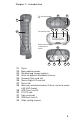
1 Elastomer overmold
2 Magnesium case front
3 Display bezel
4 Charge LED
5 Start menu button
6 Applications Manager
button
7 Microphone
8 Today screen button
9 Speaker
10 Four-way directional
button
11 Power button
12 Context menu button
13 Enter button
14 Notifi cation LED
15 Touchscreen/display
16 Accessory attachment
points (5 cm. center
to center 8-32 UNC
thread)
17 Battery door latch
18 Hand strap
19 Battery door
20 Body molding
16
18
17
19
4
2
3
7
8
9
2
13
15
1
5
6
10
11
12
14
20
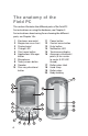
The anatomy of the
Field PC
This section illustrates the di erent parts of the Field PC.
For instructions on using the hardware, see Chapter 3.
For instructions about caring for or cleaning the di erent
parts, see Chapter 10.v