
User Manual


Table Of Contents
- Allegro CE™ Owner's Manual
- Table of Contents
- Chapter 1 Introduction
- Chapter 2 Hardware Components
- Chapter 3 Memory Configuration and Data Storage Options
- Chapter 4 Windows CE Operating System
- Chapter 5 Technical Reference
- Chapter 6 Software Developer’s Guide for Allegro CE 3.0 and CE .NET
- Chapter 7 FCC Information, Warranty, and Software License Agreement
- Chapter 8 Expansion Pods
- Index
- Table of Contents
- Chapter 1 Introduction
- Chapter 2 Hardware Components
- Case Design
- Keyboard
- Display
- System Tray Indicators
- Batteries
- Main Power Source
- Setting Battery Charge
- Battery Life
- Recharging the NiMH Battery Pack
- Battery Gauging Explained
- Battery Status Icons
- When the Battery Voltage Drops
- Power Management Feature
- Changing NiMH Battery Pack
- Alkaline Battery Holder: Inserting Batteries and Usage Information
- Storing the Allegro CE During Inactive Periods
- NiMH Battery Pack's Useful Life
- Spare NiMH Battery Packs
- Short-Term Backup Supply
- Real Time Clock
- Main Power Source
- Communication Ports
- USB/Power Dock
- PC Cards
- Expansion Pods
- Chapter 3 Memory Configuration and Data Storage Options
- Chapter 4 Windows CE Operating System
- Windows CE Overview
- CE .NET Viewers
- ActiveSync Transfer
- Downloading ActiveSync from the Internet
- Installing ActiveSync
- Establishing a First Time ActiveSync Connection
- Establishing Additional ActiveSync Connections
- New Partnership Set Up
- USB MultiSync
- USB MultiSync Connections
- Transferring Files Between the Allegro CE and the Desktop PC
- Windows Explorer
- Storing Files and Programs
- System Save/Restore Utilities
- Application Command Bars
- PTab Spreadsheet Program
- Pocket Word/WordPad
- Internet Explorer and Inbox
- Calculator Program
- Terminal Program
- Chapter 5 Technical Reference
- Chapter 6 Software Developer’s Guide for Allegro CE 3.0 and CE .NET
- Chapter 7 FCC Information, Warranty, and Software License Agreement
- Chapter 8 Expansion Pods
- Index
Page 2-40 Hardware Features
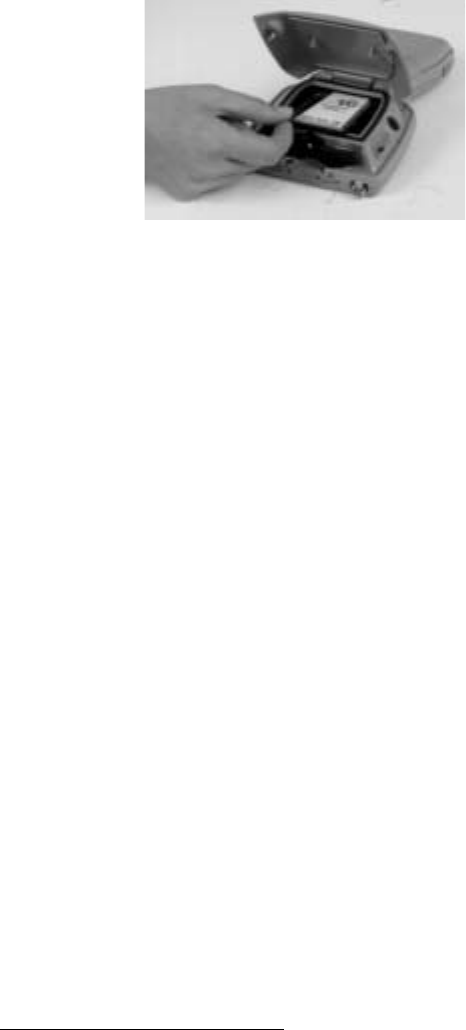
4) PC cards have a 68 pin socket on one end. Insert the card socket-
first. The front of the card should be facing the door .
❖ Important Note: Be careful when inserting and removing cards. Excess
force could damage the card and the card drive. If the system tray indicator
for the PC card activity is on, the computer is writing to the card. Do not
turn off the Allegro and remove the card until the indicator stops blinking.
Incomplete files can corrupt the data already stored on the card.
5) To remove a car d, push the eject button, grasp the card firmly, and
pull it out.
6) Close the door to the PC car d slot. Turn both screws clockwise l/4
of a turn to seal the compartment. (Because of the wide slits in the
screws you can use coins or even keys to turn the screws.)
▲ ▲
▲ ▲
▲ Displaying Information About the PC Card
You can display information about the installed PC card such as the
card type and the name of the manufacturer. In Windows CE, go to
Control Panel|System Properties|General to view this information.