
User Manual


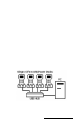
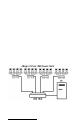
Table Of Contents
- Allegro CE™ Owner's Manual
- Table of Contents
- Chapter 1 Introduction
- Chapter 2 Hardware Components
- Chapter 3 Memory Configuration and Data Storage Options
- Chapter 4 Windows CE Operating System
- Chapter 5 Technical Reference
- Chapter 6 Software Developer’s Guide for Allegro CE 3.0 and CE .NET
- Chapter 7 FCC Information, Warranty, and Software License Agreement
- Chapter 8 Expansion Pods
- Index
- Table of Contents
- Chapter 1 Introduction
- Chapter 2 Hardware Components
- Case Design
- Keyboard
- Display
- System Tray Indicators
- Batteries
- Main Power Source
- Setting Battery Charge
- Battery Life
- Recharging the NiMH Battery Pack
- Battery Gauging Explained
- Battery Status Icons
- When the Battery Voltage Drops
- Power Management Feature
- Changing NiMH Battery Pack
- Alkaline Battery Holder: Inserting Batteries and Usage Information
- Storing the Allegro CE During Inactive Periods
- NiMH Battery Pack's Useful Life
- Spare NiMH Battery Packs
- Short-Term Backup Supply
- Real Time Clock
- Main Power Source
- Communication Ports
- USB/Power Dock
- PC Cards
- Expansion Pods
- Chapter 3 Memory Configuration and Data Storage Options
- Chapter 4 Windows CE Operating System
- Windows CE Overview
- CE .NET Viewers
- ActiveSync Transfer
- Downloading ActiveSync from the Internet
- Installing ActiveSync
- Establishing a First Time ActiveSync Connection
- Establishing Additional ActiveSync Connections
- New Partnership Set Up
- USB MultiSync
- USB MultiSync Connections
- Transferring Files Between the Allegro CE and the Desktop PC
- Windows Explorer
- Storing Files and Programs
- System Save/Restore Utilities
- Application Command Bars
- PTab Spreadsheet Program
- Pocket Word/WordPad
- Internet Explorer and Inbox
- Calculator Program
- Terminal Program
- Chapter 5 Technical Reference
- Chapter 6 Software Developer’s Guide for Allegro CE 3.0 and CE .NET
- Chapter 7 FCC Information, Warranty, and Software License Agreement
- Chapter 8 Expansion Pods
- Index

Hardware Features Page 2-37
▲▲
▲▲
▲ USB Communication
The USB/Power Dock also serves as a USB connection from the
Allegro to the desktop PC. The red LED indicator lights up when the
USB connection between the Power Dock and desktop PC is active.
The connection and communication between the desktop PC and the
Allegro is achieved through ActiveSync. The USB port is used for
connecting both single or multiple units.
USB/Power Dock Connector Pins
The interaction between the Power Dock and Allegro happens
through the connection of the six connectors on the bottom of the
Allegro. There are six pins in the Power Dock that touch the Allegro
connectors as the Allegro is placed into the Power Dock. The six pins
can be replaced if damaged or bent.
▲▲
▲▲
▲ USB Connection
To establish a connection between the Allegro and desktop PC follow
the directions in Chapter 4 in the section entitled, Establishing a
Connection Using ActiveSync.
Once you have set up and successfully connected to ActiveSync for
the first time, you only need to place the Allegro into the Power Dock
and it will automatically begin the ActiveSync connection sequence.