
User Manual


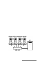
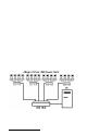
Table Of Contents
- Allegro CE™ Owner's Manual
- Table of Contents
- Chapter 1 Introduction
- Chapter 2 Hardware Components
- Chapter 3 Memory Configuration and Data Storage Options
- Chapter 4 Windows CE Operating System
- Chapter 5 Technical Reference
- Chapter 6 Software Developer’s Guide for Allegro CE 3.0 and CE .NET
- Chapter 7 FCC Information, Warranty, and Software License Agreement
- Chapter 8 Expansion Pods
- Index
- Table of Contents
- Chapter 1 Introduction
- Chapter 2 Hardware Components
- Case Design
- Keyboard
- Display
- System Tray Indicators
- Batteries
- Main Power Source
- Setting Battery Charge
- Battery Life
- Recharging the NiMH Battery Pack
- Battery Gauging Explained
- Battery Status Icons
- When the Battery Voltage Drops
- Power Management Feature
- Changing NiMH Battery Pack
- Alkaline Battery Holder: Inserting Batteries and Usage Information
- Storing the Allegro CE During Inactive Periods
- NiMH Battery Pack's Useful Life
- Spare NiMH Battery Packs
- Short-Term Backup Supply
- Real Time Clock
- Main Power Source
- Communication Ports
- USB/Power Dock
- PC Cards
- Expansion Pods
- Chapter 3 Memory Configuration and Data Storage Options
- Chapter 4 Windows CE Operating System
- Windows CE Overview
- CE .NET Viewers
- ActiveSync Transfer
- Downloading ActiveSync from the Internet
- Installing ActiveSync
- Establishing a First Time ActiveSync Connection
- Establishing Additional ActiveSync Connections
- New Partnership Set Up
- USB MultiSync
- USB MultiSync Connections
- Transferring Files Between the Allegro CE and the Desktop PC
- Windows Explorer
- Storing Files and Programs
- System Save/Restore Utilities
- Application Command Bars
- PTab Spreadsheet Program
- Pocket Word/WordPad
- Internet Explorer and Inbox
- Calculator Program
- Terminal Program
- Chapter 5 Technical Reference
- Chapter 6 Software Developer’s Guide for Allegro CE 3.0 and CE .NET
- Chapter 7 FCC Information, Warranty, and Software License Agreement
- Chapter 8 Expansion Pods
- Index

Page 2-34 Hardware Features
Communication Ports
The Allegro CE has five possible communication ports:
❏ Two 9 pin serial ports (located on the top of the case)
❏ One infrared port (on top of the case)
❏ One USB port (available through the optional USB/Power Dock)
❏ One internal expansion port (available for most expansion pods)
Some of these ports are recessed to protect them in case the Allegro is
dropped. They are also completely sealed.
▲▲
▲▲
▲ 9 Pin Serial Communication Ports
The standard 9 pin serial communication ports (COM1 and COM2)
allow for the simultaneous operation of two serial devices such as
printers, modems, and bar code wands. Additional power is
provided on COM1 to power bar code wands and other sensors. The
data transfer rate on these ports ranges from 300 baud to 115 Kbaud.
Rubber connector protectors keep dirt and moisture out of the ports.
The ports are sealed without the protectors.
Be sure to use the serial communication cable (9 pin to 9 pin)
included with the Allegro to connect the Allegro to a desktop PC. A
wiring diagram of the cable is shown in Chapter 5, Technical Reference.
Note that a standard ‘straight through’ serial cable will not work.
9 Pin D Connector Pinouts
Pin #
1 Data Carrier Detect (DCD) Input
2 Receive Data (RCD) Input
3 Transmit Data (TXD) Output
4 Data Terminal Ready (DTR) Output
5 Ground (GND)
6 Data Set Ready (DSR) Input
7 Request To Send (RTS) Output
8 Clear To Send (CTS) Input
9 Ring Indicator (RI) Input