
Network Hardware User Manual


Appendix B Port Descriptions and LED Status
IV User’s Guide
STATUS LED STATES
This section describes Status LED states on all modules.
Interpreting Status LEDs for the Management
Modules
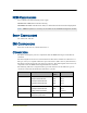
The Status LEDs indicate whether the management module is operating properly. The
following table describes the status possibilities for each.
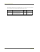
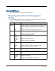
LED LED Color Meaning of the LED
CPU
Utilization
green Consists of an array of five LEDs that indicate the current level of CPU
utilization. Utilization is defined as the amount of traffic detected on the
device at any given time. The CPU utilization LEDs represent the
following percentages of possible utilization: 5%, 10%, 25%, 50%, and
90%.
off When all are off, indicates less than 5 percent CPU use.
POWER green Indicates the system is receiving power.
off Indicates the system is not receiving power.
red Indicates the power has a problem.
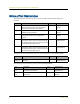
STATUS blinking
green
Indicates the system is operational.
blinking
amber
Indicates the system is booting up.
off Indicates the module is not operational.
HA green Indicates the module is a master in a redundancy cluster.
red Indicates the module is ineligible to be a backup.
amber Indicates the module is a backup in a redundancy cluster.
off Indicates that no HA activity has been defined.
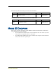
ALARM red Indicates an alarm which could mean a system failure.
blinking red Indicates a self-test failure during the bootup process.
off Indicates the system has not detected an event or error at the current
time.
FLASH green Indicates the flash card is installed.
blinking
green
Indicates flash card activity.
off Indicates no flash card loaded in the flash card slot.