Security Products SSG 20 Hardware Installation and Configuration Guide Juniper Networks, Inc. 1194 North Mathilda Avenue Sunnyvale, CA 94089 USA 408-745-2000 www.juniper.
Copyright Notice Copyright © 2006 Juniper Networks, Inc. All rights reserved. Juniper Networks and the Juniper Networks logo are registered trademarks of Juniper Networks, Inc. in the United States and other countries. All other trademarks, service marks, registered trademarks, or registered service marks in this document are the property of Juniper Networks or their respective owners. All specifications are subject to change without notice.
Table of Contents About This Guide 5 Organization .................................................................................................... 6 WebUI Conventions ......................................................................................... 6 CLI Conventions............................................................................................... 7 Obtaining Documentation and Technical Support ............................................
SSG 20 Hardware Installation and Configuration Guide Using Telnet ............................................................................................ 30 Default Device Settings .................................................................................. 31 Basic Device Configuration ............................................................................ 33 Root Admin Name and Password ............................................................ 33 Date and Time..........................
About This Guide The Juniper Networks Secure Services Gateway (SSG) 20 device is an integrated router and firewall platform that provides Internet Protocol Security (IPSec) virtual private network (VPN) and firewall services for a branch office or a retail outlet. Juniper Networks offers two models of the SSG 20 device: SSG 20, which supports auxiliary (AUX) connectivity SSG 20-WLAN, which supports integrated 802.
SSG 20 Hardware Installation and Configuration Guide Organization This guide contains the following sections: Chapter 1, “Hardware Overview,” describes the chassis and components of an SSG 20 device. Chapter 2, “Installing and Connecting the Device,” describes how to mount an SSG 20 device and how to connect cables and power to the device. Chapter 3, “Configuring the Device,” describes how to configure and manage an SSG 20 device and how to perform some basic configuration tasks.
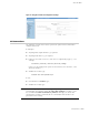
About This Guide Figure 1: Navigational Path and Configuration Settings CLI Conventions The following conventions are used to present the syntax of CLI commands in examples and in text. In examples: Anything inside square brackets [ ] is optional. Anything inside braces { } is required. If there is more than one choice, each choice is separated by a pipe ( | ).
SSG 20 Hardware Installation and Configuration Guide Obtaining Documentation and Technical Support To obtain technical documentation for any Juniper Networks product, visit www.juniper.net/techpubs/. For technical support, open a support case using the Case Manager link at http://www.juniper.net/support/ or call 1-888-314-JTAC (within the United States) or 1-408-745-9500 (outside the United States).
Chapter 1 Hardware Overview This chapter provides detailed descriptions of the SSG 20 chassis and its components.
SSG 20 Hardware Installation and Configuration Guide Port and Power Connectors This section describes and displays the location of the built-in ports and power connectors. Refer to the following figure for built-in port locations and Table 1 for the power connector descriptions. Figure 2: Built-in Port and Mini-PIM Location Mini-PIM 1 1 Mini-PIM 2 2 SSG 20 LI NK POWER PI M 1 STATUS PI M 2 802.
Front Panel This section describes the following elements on the front panel of an SSG 20 device: System Status LEDs Port Descriptions Mini Physical Interface Module Port Descriptions System Status LEDs The system status LEDs display information about critical device functions. Figure 3 illustrates the position of each status LED on the front of the SSG 20-WLAN device. The WLAN LEDs are only present on the SSG 20-WLAN device. Figure 3: Status LEDs 1 POWER PI M 1 STATUS PI M 2 2 802.
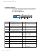
SSG 20 Hardware Installation and Configuration Guide Name Color Status Description PIM 2 Green On steadily Indicates that the mini PIM is functioning. Blinking Indicates that the mini PIM is passing traffic. Off Indicates that the mini PIM is not operational. On steadily Indicates that a wireless connection is established but there is no link activity. Blinking slowly Indicates that a wireless connection is established. The baud rate is proportional to the link activity.
Port Descriptions This section explains the purpose and function of the following: Ethernet Ports Console Port AUX Port Ethernet Ports Five 10/100 Ethernet ports provide LAN connections to hubs, switches, local servers, and workstations. You can also designate an Ethernet port for management traffic. The ports are labeled 0/0 through 0/4. For the default zone bindings for each Ethernet port, see “Default Device Settings” on page 31.
SSG 20 Hardware Installation and Configuration Guide AUX Port The auxiliary (AUX) port is an RJ-45 serial port wired as data terminal equipment (DTE) that can be connected to a modem to allow remote administration. We do not recommend using this port for regular remote administration. The AUX port is typically assigned to be the backup serial interface. The baud rate is adjustable from 9600 bps to 115200 bps and requires hardware flow control.
Table 4: Mini PIM LED States on the SSG 20 Type Name Color State ADSL 2/2+ SYNC Green On steadily Indicates that the ADSL interface is trained (Annex A and B) TX/RX ISDN (BRI) CH B1 Green Green Blinking Indicates training is in progress Off Indicates that the interface is idle Blinking Indicates that traffic is passing through Off Indicates that no traffic is passing through On steadily Indicates that B-Channel 1 is active Off CH B2 Green ALARM Yellow Yellow Green CD TX/RX Green
SSG 20 Hardware Installation and Configuration Guide Back Panel This section describes the following elements on the back panel of an SSG 20 device: Power Adapter Radio Transceivers Grounding Lug Antennae Types USB Port Figure 6: Back Panel of an SSG 20-WLAN Device Antenna B Antenna A USB port Device security lock L OCK B USB RESET DC POWER 12V 4A A Power adapter Grounding Reset lug pinhole Power Adapter The POWER LED on the front panel of a device either glows green or is off
Grounding Lug A one-hole grounding lug is provided on the rear of the chassis to connect the device to earth ground (see Figure 6). To ground the device before connecting power, connect a grounding cable to earth ground and then attach the cable to the lug on the rear of the chassis.
SSG 20 Hardware Installation and Configuration Guide Antennae Types The SSG 20-WLAN device supports three types of custom-built radio antennae: Diversity antennae — The diversity antennae provide 2dBi directional coverage and a fairly uniform level of signal strength within the area of coverage and are suitable for most installations. This type of antennae is shipped with the device. External omnidirectional antenna — The external antenna provides 2dBi omnidirectional coverage.
Chapter 2 Installing and Connecting the Device This chapter describes how to mount an SSG 20 device and connect cables and power to the device.
SSG 20 Hardware Installation and Configuration Guide Before You Begin The location of the chassis, the layout of the mounting equipment, and the security of your wiring room are crucial for proper system operation. WARNING: To prevent abuse and intrusion by unauthorized personnel, install the SSG 20 device in a secure environment.
To front-mount an SSG 20 device onto a standard 19-inch equipment rack, perform the following steps: Figure 7: SSG 20 Front-mount Power Supply 1. Align the power supply rack-mount ear to the left-front edge of the device. 2. Place the screws in the holes and use a phillips screwdriver to secure them. 3. Align the other rack-mount ear to the right-front edge of the device. 4. Place the screws in the holes and use a phillips screwdriver to secure them. 5.
SSG 20 Hardware Installation and Configuration Guide To desk-mount an SSG 20 device, perform the following steps: Figure 9: SSG 20 Desk-mount 1. Attach the desktop stand to the side of the device. We recommend using the side closest to the power adapter. 2. Place the mounted device on the desktop. 3. Plug in the power adapter and connect the power supply to the power outlet. Connecting Interface Cables to a Device To connect the interface cable to a device, perform the following steps: 1.
Connecting a Device to a Network An SSG 20 device provides firewall and general security for networks when it is placed between internal networks and the untrusted network.
SSG 20 Hardware Installation and Configuration Guide Ethernet Ports To establish a high-speed connection, connect the provided Ethernet cable from the Ethernet port marked 0/0 on an SSG 20 device to the external router. The device autosenses the correct speed, duplex, and MDI/MDIX settings. Serial (AUX/Console) Ports You can connect to the untrusted network with an RJ-45 straight-through serial cable and an external modem.
Figure 11: Microfilter and Splitter on Your Network Connection DATA ADSL 1 2+ ADSL 2 /2 + SYNC 2 SYNC TX RX SSG 20 TX/RX LI NK TX/RX POWER PI M 1 802.11a STATUS PI M 2 b/g WLAN AUX VOICE CONSOL E 0 /0 10/100 0 /1 10 /100 0 /2 10 /100 0/4 10 /100 0/ 5 10 /100 ISDN, T1, E1, and V.92 Mini PIMs To connect the mini PIMs to a device, perform the following steps: 1. Have ready a length of the type of cable used by the interface. 2.
SSG 20 Hardware Installation and Configuration Guide Wireless Antennae If you are using the wireless interface, you need to connect the provided antennae on the device. If you have the standard 2dB diversity antennae, use screws to attach them onto the posts marked A and B at the back of the device. Bend each antenna at its elbows, making sure not to put pressure on the bulkhead connectors.
Chapter 3 Configuring the Device ScreenOS software is preinstalled on an SSG 20 device. When the device is powered on, it is ready to be configured. While the device has a default factory configuration that allows you to initially connect to the device, you need to perform further configuration for your specific network requirements.
SSG 20 Hardware Installation and Configuration Guide Accessing a Device You can configure and manage a device in several ways: Console: The Console port on the device allows you to access the device through a serial cable connected to your workstation or terminal. To configure the device, you enter ScreenOS command line interface (CLI) commands on your terminal or in a terminal-emulation program on your workstation.
3. Launch a serial terminal-emulation program on your workstation. The required settings to launch a console session are as follows: Baud rate: 9600 Parity: None Data bits: 8 Stop bit: 1 Flow Control: None 4. If you have not yet changed the default login for the admin name and password, enter netscreen at both the login and password prompts. (Use lowercase letters only. The login and password fields are both case-sensitive.
SSG 20 Hardware Installation and Configuration Guide Figure 14: WebUI Login Prompt 4. If you have not yet changed the default login for the admin name and password, enter netscreen at both the admin name and password prompts. (Use lowercase letters only. The login and password fields are both case-sensitive.) Using Telnet To establish a Telnet connection, perform the following steps: 1. Connect your workstation to the 0/2 — 0/4 port (bgroup0 interface in the Trust zone) on the device. 2.
Default Device Settings This section describes the default settings and operation of an SSG 20 device. Table 5 shows the default zone bindings for ports on the devices.
SSG 20 Hardware Installation and Configuration Guide To unset ethernet0/3 from bgroup0 and assign it to the Trust zone with a static IP address of 192.168.3.1/24, use the WebUI or CLI as follows: WebUI Network > Interfaces > List > Edit (bgroup0) > Bind Port: deselect ethernet0/3, then click Apply. List > Edit (ethernet0/3): Enter the following, then click Apply: Zone Name: Trust (select) IP Address/Netmask: 192.168.3.
Basic Device Configuration This section describes the following basic configuration settings: Root Admin Name and Password Date and Time Bridge Group Interfaces Administrative Access Management Services Hostname and Domain Name Default Route Management Interface Address Backup Untrust Interface Configuration Root Admin Name and Password The root admin user has complete privileges for configuring an SSG 20 device.
SSG 20 Hardware Installation and Configuration Guide Date and Time The time set on an SSG 20 device affects events such as the setup of VPN tunnels. The easiest way to set the date and time on the device is to use the WebUI to synchronize the device system clock with the workstation clock. To configure the date and time on a device, use the WebUI or CLI as follows: WebUI 1. Configuration > Date/Time: Click the Sync Clock with Client button.
CLI unset interface bgroup0 port ethernet0/3 unset interface bgroup0 port ethernet0/4 set interface bgroup1 port ethernet0/3 set interface bgroup1 port ethernet0/4 set interface bgroup1 port wireless0/2 set interface bgroup1 zone DMZ set interface bgroup1 ip 10.0.0.1/24 save Administrative Access By default, anyone in your network can manage a device if they know the login and password.
SSG 20 Hardware Installation and Configuration Guide Hostname and Domain Name The domain name defines the network or subnetwork that the device belongs to, while the hostname refers to a specific device. The hostname and domain name together uniquely identify the device in the network.
Backup Untrust Interface Configuration The SSG 20 device allows you to configure a backup interface for untrust failover. To set a backup interface for untrust failover, perform the following steps: 1. Set the backup interface in the Null security zone with the unset interface interface [port interface] CLI command. 2. Bind the backup interface to the same security zone as the primary interface with the set interface interface zone zone_name CLI command.
SSG 20 Hardware Installation and Configuration Guide Once you have set an SSID to the wireless0/0 interface, you can access the device using the default wireless0/0 interface IP address in the steps described in “Accessing a Device” on page 28. Figure 15 shows the default configuration for the SSG 20-WLAN device.
Table 7: Wireless Authentication and Encryption Options Authentication Encryption Open Allows any wireless client to access the device Shared-key WEP shared-key WPA-PSK AES/TKIP with pre-shared key WPA AES/TKIP with key from RADIUS server WPA2-PSK 802.11i compliant with a pre-shared key WPA2 802.11i compliant with a RADIUS server WPA-Auto-PSK Allows WPA and WPA2 type with pre-shared key WPA-Auto Allows WPA and WPA2 type with RADIUS server 802.
SSG 20 Hardware Installation and Configuration Guide 5. Activate wireless changes. Wireless > General Settings > Click Activate Changes. CLI 1. Set the WLAN country code and IP address. set wlan country-code {code_id} set interface wireless_interface ip ip_addr/netmask 2. Set the SSID. set ssid name name_str set ssid name_str authentication auth_type encryption encryption_type set ssid name_str interface interface (optional) set ssid name_str key-id number 3. Set the WLAN mode.
Mini PIM Configuration This section explains how to configure the mini physical interface modules (PIMs): ADSL2/2+ Interface ISDN Interface T1 Interface E1 Interface V.92 Modem Interface ADSL2/2+ Interface Your network uses the ADSL2/2+ interface adslx/0, with x representing the mini PIM slot (1 or 2), on the device to connect to the service provider’s network through an Asynchronous Transfer Mode (ATM) virtual circuit.
SSG 20 Hardware Installation and Configuration Guide Virtual Circuits To add virtual circuits, you create subinterfaces to the ADSL2/2+ interface. You can create up to 10 ADSL2/2+ subinterfaces. For example, to create a new subinterface named adsl1/0.1 bound to the predefined zone named Untrust, use the WebUI or CLI as follows: WebUI Network > Interfaces > List > New ADSL Sub-IF: Enter the following, then click Apply: Interface Name: adsl1/0.
WebUI Network > Interfaces > List > Edit (for the adsl1/0 interface): Enter the following, then click Apply: VPI/VCI: 1 / 32 Multiplexing Method: LLC (selected) CLI set interface adsl1/0 pvc 1 32 mux llc save PPPoE or PPPoA An SSG 20 device includes both PPPoE and PPPoA clients to connect to the service provider’s network over the ADSL link. PPPoE is the most common form of ADSL encapsulation and is intended for termination on each host on your network.
SSG 20 Hardware Installation and Configuration Guide Static IP Address and Netmask If your service gave you a specific, fixed IP address and netmask for your network, then configure the IP address and netmask for the network and the IP address of the router port connected to the device. You need to also specify that the device is to use the static IP address.
CLI set interface bgroup0 dhcp server option dns1 1.1.1.152 save For more information about configuring the ADSL and ADSL2/2+ interfaces, refer to the Concepts & Examples ScreenOS Reference Guide. ISDN Interface Integrated Services Digital Network (ISDN) is a set of standards for digital transmission over different media created by the Consultative Committee for International Telegraphy and Telephone (CCITT) and International Telecommunications Union (ITU).
SSG 20 Hardware Installation and Configuration Guide AT&T Pub 54014 ITU G.751, G.703 To configure the T1 mini PIM, use the WebUI or CLI as follows: WebUI Network > Interfaces > List > Edit (serial1/0): Enter or select the following, then click OK: WAN Configure: main link WAN Encapsulation: cisco-hdlc Click Apply Fixed IP: (select) IP Address/Netmask 172.18.1.1/24 CLI set interface serial1/0 encap cisco-hdlc set interface serial1/0 ip 172.18.1.
set ppp profile “junipertest” auth local-name “juniper” set ppp profile “junipertest” auth secret “password” set interface serial1/0 ppp profile “junipertest” set interface serial1/0 ip 172.18.1.1/24 set user “server” type wan set user “server” password “server” For information on how to configure the E1 interface, refer to the Concepts & Examples ScreenOS Reference Guide. V.92 Modem Interface The V.92 interface provides an internal analog modem to establish a PPP connection to a service provider.
SSG 20 Hardware Installation and Configuration Guide Basic Firewall Protections The devices are configured with a default policy that permits workstations in the Trust zone of your network to access any resource in the Untrust security zone, while outside computers are not allowed to access or start sessions with your workstations. You can configure policies that direct the device to permit outside computers to start specific kinds of sessions with your computers.
Resetting a Device to Factory Defaults If you lose the admin password, you can reset the device to its default settings. This action destroys any existing configurations but restores access to the device. WARNING: Resetting the device deletes all existing configuration settings and disables all existing firewall and VPN services. You can restore the device to its default settings in one of the following ways: Using a Console connection.
SSG 20 Hardware Installation and Configuration Guide 50 Resetting a Device to Factory Defaults
Chapter 4 Servicing the Device This chapter describes service and maintenance procedures for an SSG 20 device. It contains the following sections: NOTE: “Required Tools and Parts” on this page “Replacing a Mini-Physical Interface Module” on this page “Upgrading Memory” on page 54 For safety warnings and instructions, refer to the Juniper Networks Security Products Safety Guide. The instructions in the guide warn you about situations that could cause bodily injury.
SSG 20 Hardware Installation and Configuration Guide Removing a Blank Faceplate To maintain proper airflow through the SSG 20 device, blank faceplates should remain over slots that do not contain mini PIMs. Do not remove a blank faceplate unless you are installing a mini PIM in its empty slot. To remove a blank faceplate, perform the following steps: 1. Place an electrostatic bag or antistatic mat on a flat, stable surface on which you intend to place the mini PIM. 2.
8. Grasp the screws on each side of the mini PIM faceplate and slide the mini PIM out of the device. Place the mini PIM in the electrostatic bag or on the antistatic mat. Figure 16: Removing a Mini PIM 9. If you are not reinstalling a mini PIM into the empty slot, install a blank faceplate over the slot to maintain proper airflow. Installing a Mini PIM To install a mini PIM, perform the following steps: 1.
SSG 20 Hardware Installation and Configuration Guide 6. If necessary, arrange the cables to prevent them from dislodging or developing stress points: a. Secure the cables so that they are not supporting their own weight as they hang to the floor. b. Place any excess cables out of the way in neatly coiled loops. c. Use fasteners to maintain the shape of the cable loops. 7. Unplug the power adapter from the device. Verify that the POWER LED glows steadily green after you press the power button. 8.
6. Release the 128 MB DIMM DRAM by pressing your thumbs outward on the locking tabs on each side of the module so that the tabs move away from the module. Figure 19: Unlocking the Memory Module 7. Grip the long edge of the memory module and slide it out. Set it aside. Figure 20: Removing Module Slots 8. Insert the 256 MB DIMM DRAM into the slot. Exerting even pressure with both thumbs upon the upper edge of the module, press the module downward until the locking tabs click into position.
SSG 20 Hardware Installation and Configuration Guide 9. Place the memory-card cover over the slot. 10. Use the phillips screwdriver to tighten the screws, securing the cover to the device.
Appendix A Specifications This appendix provides general system specifications for an SSG 20 device.
SSG 20 Hardware Installation and Configuration Guide Physical Table 8: SSG 20 Physical Specifications Description Value Chassis dimensions 294 mm x 194.8 mm x 44 mm (11.5 inches x 7.7 inches x 2 inches) Device weight 1.53 kg (3.3 lbs) without PIMs installed ISDN PIM 70g ADSL Annex A PIM 106g ADSL Annex B PIM 106g T1 PIM 75g E1 PIM 75g V.92 PIM 79g Electrical Table 9: SSG 20 Electrical Specifications Item Specification DC input voltage 12V DC system current rating 3 - 4.
Certifications Safety CAN/CSA-C22.2 No.
SSG 20 Hardware Installation and Configuration Guide T1 Interface FCC Part 68 - TIA 968 Industry Canada CS-03 UL 60950-1 Applicable requirements for TNV circuit with outside plant lead connection Connectors Figure 22 shows the location of the pins on the RJ-45 connector. Figure 22: RJ-45 Pinouts 1 2 3 4 5 6 7 8 Table 11 lists the RJ-45 connector pinouts.
Figure 23 shows the location of the pins on the DB-9 female connector. Figure 23: DB-9 Female Connector Table 12 provides the DB-9 connector pinouts.
SSG 20 Hardware Installation and Configuration Guide 62 Connectors
Appendix B Initial Configuration Wizard This appendix provides detailed information about the Initial Configuration Wizard (ICW) for an SSG 20 device. After you have physically connected your device to the network, you can use the ICW to configure the interfaces that are installed on your device.
SSG 20 Hardware Installation and Configuration Guide 1. Rapid Deployment Window Figure 24: Rapid Deployment Window If your network uses NetScreen-Security Manager (NSM), you can use a Rapid Deployment configlet to automatically configure the device. Obtain a configlet from your NSM administrator, select Yes, select Load Configlet from:, browse to the file location, then click Next. The configlet sets up the device for you, so you don’t need to use the following steps to configure the device.
3. WLAN Access Point Window If you are using the device in the WORLD or ETSI regulatory domain, you must choose a country code. Select the appropriate options, then click Next. Figure 26: Wireless Access Point Country Code Window 4. Physical Interface Window On the interface-to-zone bindings screen, you set the interface to which you want to bind the Untrust security zone. Bgroup0 is prebound to the Trust security zone. Eth0/1 is bound to the DMZ security zone but is optional.
SSG 20 Hardware Installation and Configuration Guide 5. ADSL2/2+ Interface Window If you have the ADSL2/2+ mini PIM installed in your device, you can configure the adslx/0 interface using the following window. NOTE: If you have two ADSL2/2+ mini-PIMs installed on your device, you cannot configure the Multi-link feature with the ICW. To configure ML ADSL, refer to the Concepts & Examples ScreenOS Reference Guide.
Table 13: Fields in ADSL Interface Configuration Window Field Description Information from Service Provider: VPI/VCI VPI/VCI values to identify the permanent virtual circuit. Multiplexing Method ATM multiplexing method (LLC is the default). RFC1483 Protocol Mode Protocol mode setting (Bridged is the default). Operating Mode Operating mode for the physical line (Auto is the default).
SSG 20 Hardware Installation and Configuration Guide 6. T1 Interface Windows If you have the T1 mini-PIM installed in your device and you selected the Frame Relay option, the following windows are displayed: NOTE: T1 Physical Layer Tab Window T1 Frame Relay Tab Window If you have two T1 mini-PIMs installed on your device and you select the Multi-link option, you will see two Physical Layer tabs.
Table 14: Fields in T1 Physical Layer Tab Window Field Description Clocking Sets the transmit clock on the interface. Line Buildout Sets the distance at which an interface drives a line. Default setting is 0 - 132 feet. Line Encoding Sets the line encoding format on the interface: Auto Mark Inversion 8-bits zero suppression Bye Encoding Sets the byte encoding on the T1 interface to use 7 bits per byte or 8 bits per byte. Default is 8 bits per byte. Frame Checksum Sets the size of checksum.
SSG 20 Hardware Installation and Configuration Guide Figure 30: T1 Frame Relay Tab Window Table 15: Fields in T1 Frame Relay Tab Window Field Description No-Keepalive checkbox Enables no-keepalives. Type Sets the frame relay LMI type: ANSI: American National Standards Institute supports data rates up to 8Mbps downstream and 1Mbps upstream. ITU: International Telecommunications Union supports data rates of 6.144 Mbps downstream and 640 kbps upstream.
If you have the T1 mini-PIM installed in your device and you selected the PPP option, the following additional windows are displayed: PPP Option with PPP Tab Window PPP Option with Peer User Tab Window Figure 31: PPP Option with PPP Tab Window Table 16: Fields in PPP Option with PPP Tab Window Field Description PPP Profile Name Sets the name of the PPP profile Authentication Sets the authentication type Local User Sets the name of the local user Password Sets the password for the local use
SSG 20 Hardware Installation and Configuration Guide Figure 32: PPP Option with Peer User Tab Window Table 17: Fields in PPP Option with Peer User Tab Window Field Description Peer User Sets the name of the peer user Password Sets the password for the peer user specified in the Peer User text field Status Enables or disables PPP If you have the T1 mini-PIM installed in your device and you selected the Cisco HDLC option, the following window is displayed: Figure 33: Cisco HDLC Option with Cisco HDL
Table 18: Fields in Cisco HDLC Option with Cisco HDLC Tab Window Field Description Interface IP Sets the IP address for the T1 Cisco HDLC interface Netmask Sets the netmask for the T1 Cisco HDLC interface Gateway Sets the gateway address for the T1 Cisco HDLC interface 7.
SSG 20 Hardware Installation and Configuration Guide Table 19: Fields in E1 Physical Layer Tab Window Field Description Clocking Sets the transmit clock on the interface. Frame Checksum Sets the size of checksum. Default is 16. Framing Mode Sets the framing format. Default is without CRC4. Idle Cycles Flag Sets the value that the interface transmits during idle cycles.
Field Description Interface IP Sets the IP address for the subinterface Netmask Sets the netmask for the subinterface Gateway Sets the gateway address for the subinterface To configure the E1 interface with PPP options, see “PPP Option with PPP Tab Window” on page 71. To configure the E1 interface with the Cisco HDLC, see “Cisco HDLC Option with Cisco HDLC Tab Window” on page 72. 8.
SSG 20 Hardware Installation and Configuration Guide Table 21: Fields in ISDN Physical Layer Tab Window Field Description Switch Type Sets the service provider switch type: att5e: At&T 5ESS ntdms100: Nortel DMS 100 ins-net: NTT INS-Net etsi: European variants ni1: National ISDN-1 SPID1 Service Provider ID, usually a seven-digit telephone number with some optional numbers. Only the DMS-100 and NI1 switch types require SPIDs.
Figure 37: ISDN Connection Tab Window Table 22: Fields in ISDN Connection Tab Window Field Description PPP Profile Name Sets a PPP profile name to the ISDN interface. Authentication Sets the PPP authentication type: Any CHAP: Challenge Handshake Authentication Protocol PAP: Password Authentication Protocol None Local User Sets the local user. Password Sets the password for the local user. Static IP checkbox Enables a static IP address for the interface.
SSG 20 Hardware Installation and Configuration Guide Field Description Dialer Pool (Dialer only) Sets the dialer pool name for the dialer interface. Netmask Sets the netmask. Gateway Sets the gateway address. 9. V.92 Modem Interface Window If you have the V.
Figure 39: Eth0/0 Interface Window Table 24: Fields in Eth0/0 Interface Window Field Description Dynamic IP via DHCP Enables the device to receive an IP address for the Untrust zone interface from a service provider. Dynamic IP via PPPoE Enables the device to act as a PPPoE client, receiving an IP address for the Untrust zone interface from a service provider. Enter the username and password assigned by the service provider.
SSG 20 Hardware Installation and Configuration Guide Figure 40: Eth0/1 Interface Window Table 25: Fields in Eth0/1 Interface Window Field Description Dynamic IP via DHCP Enables the device to receive an IP address for the DMZ interface from a service provider. Static IP Assigns a unique and fixed IP address to the DMZ interface. Enter the DMZ interface IP and netmask. 12. Bgroup0 Interface (Trust Zone) Window The bgroup0 interface can have a static or a dynamic IP address assigned via DHCP.
Table 26: Fields in Bgroup0 Interface Window Field Description Dynamic IP via DHCP Enables the device to receive an IP address for the Trust zone interface from a service provider. Static IP Assigns a unique and fixed IP address to the Trust zone interface. Enter the Trust zone interface IP address and netmask. 13. Wireless0/0 Interface (Trust Zone) Window If you are configuring the SSG 20-WLAN device, you must set a Service Set Identifier (SSID) before the wireless0/0 interface can be activated.
SSG 20 Hardware Installation and Configuration Guide Table 27: Fields in Wireless0/0 Interface Window Field Description Wlan Mode Sets the WLAN radio mode: 5G (802.11a). 2.4G (802.11b/g). Both (802.11a/b/g). SSID Sets the SSID name. Authentication and Encryption Sets the WLAN interface authentication and encryption: Open authentication, the default, allows anyone to access the device. There is no encryption for this authentication option.
Check your interface configuration, then click Next when ready to proceed. The Physical Ethernet DHCP Interface window appears. 15. Physical Ethernet DHCP Interface Window Select Yes to enable your device to assign IP addresses to your wired network via DHCP. Enter the IP address range that you want your device to assign to clients using your network, then click Next. Figure 44: Physical Ethernet DHCP Interface Window 16.
SSG 20 Hardware Installation and Configuration Guide 17. Confirmation Window Confirm your device configuration and change as needed. Click Next to save, reboot the device, and run the configuration. Figure 46: Confirmation Window After the device reboots with the saved system configuration, the WebUI login prompt appears. For information on how to access the device using the WebUI, refer to “Using the WebUI” on page 29.
Index A AAL5 multiplexing .........................................................41 ADSL configuring interface ...............................................41 connecting the cable ...............................................24 connecting the port .................................................24 Annex A ..........................................................................24 Annex B ..........................................................................24 antennae ...........................
SSG 20 Hardware Installation and Configuration Guide S static IP address............................................................. 41 U Untrust zone, configuring backup interface ............... 37 V Virtual Path Identifier/Virtual Channel Identifier See VPI/VCI VPI/VCI configuring ............................................................... 42 values ........................................................................ 41 W wireless antennae ....................................................