M10i Internet Router PIC Guide Juniper Networks, Inc. 1194 North Mathilda Avenue Sunnyvale, California 94089 USA 408-745-2000 www.juniper.
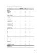
M10i Internet Router PIC Guide This guide provides an overview and description of the Physical Interface Cards (PICs) supported by the Juniper Networks M10i Internet router. The PICs are described alphabetically. Table 1 on page 3 lists the PICs supported by the M10i router. PICs provide the physical connection to various network media types. The PICs are inserted into a slot in a router. You can install PICs of different media types on the same router as long as the router supports those PICs.
Table 1: PICs Supported in the M10i Internet Router Ports First JUNOS Support PIC Slots Required Page ATM2 DS3 IQ 4 6.1 1 slot 9 ATM2 E3 IQ 2 6.1 1 slot 11 ATM2 OC3/STM1 IQ 2 6.1 1 slot 13 ATM2 OC12/STM4 IQ 1 6.1 1 slot 16 1 6.1 1 slot 22 Channelized DS3 IQ 4 6.1 1 slot 18 Channelized E1 IQ 10 6.1 1 slot 20 Channelized OC12 IQ 1 6.1 1 slot 24 Channelized OC3 IQ 1 7.1 1 slot 26 Channelized STM1 IQ 1 6.1 1 slot 28 Channelized T1 IQ 10 7.
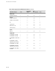
M10i Internet Router PIC Guide Table 1: PICs Supported in the M10i Internet Router (continued) Ports First JUNOS Support PIC Slots Required Page 4 7.6R3 1 slot 51 Adaptive Services II 0 6.4 1 slot 5 Adaptive Services II FIPS 0 7.2 1 slot 7 ES 0 6.1 1 slot 42 Link Services 0 6.1 1 slot 54 MultiServices 100 0 8.1 1 slot 55 Tunnel Services 0 6.1 1 slot 76 2 6.1 1 slot 40 SONET/SDH OC3c/STM1 2 6.1 1 slot 57 SONET/SDH OC3c/STM1 4 6.
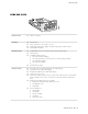
Adaptive Services II PIC Adaptive Services II PIC Software release ■ JUNOS 6.4 and later Description ■ Supports tunnel services. This feature is included with the PIC and does not require an individual license. ■ Individual licenses must be purchased for additional services. ■ Power requirement: 0.
M10i Internet Router PIC Guide Table 2: Adaptive Services PICs Software Features (continued) Network Address Translation (NAT) for IP addresses 6.4 Port Address Translation (PAT) for port numbers 6.4 IP Security (IPSec) encryption 6.4 Active flow monitoring exports cflowd version 5 and version 8 records 6.4 Active flow monitoring exports version 9 records, based on RFC 3954 (IP v4 templates only) 8.3 Passive flow monitoring – Passive flow collection – Flow-tap 8.
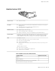
Adaptive Services II FIPS PIC Adaptive Services II FIPS PIC Software release ■ JUNOS 7.2 and later Description ■ JUNOS-FIPS requires an Adaptive Services II FIPS PIC for external IPSec connections. See the Secure Configuration Guide for Common Criteria and JUNOS-FIPS for more information. ■ Supports tunnel services. This feature is included with the PIC and does not require an individual license.
M10i Internet Router PIC Guide LEDs Status LED, one tricolor: ■ Off—PIC is offline and it is safe to remove it from the chassis. ■ Green—PIC is operating normally. ■ Amber—PIC is initializing. ■ Red—PIC has an error or failure and no further harm can be done by removing it from the chassis. Application LED, one tricolor: 8 ■ ■ Off—Service is not running. ■ Green—Service is running under acceptable load. ■ Amber—Service is overloaded.
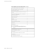
ATM2 DS3 IQ PIC ATM2 DS3 IQ PIC Software release ■ JUNOS 6.1 and later Description ■ Four DS3 ports ■ Power requirement: 0.41 A @ 48 V (20.0 W) ■ Intelligent queuing (IQ) PICs support fine-grained queuing per logical interface.
M10i Internet Router PIC Guide Cables and connectors LEDs ■ 10 ft (3.
ATM2 E3 IQ PIC ATM2 E3 IQ PIC Software release ■ JUNOS 6.1 and later Description ■ Two E3 ports ■ Power requirement: 0.41 A @ 48 V (20 W) ■ Intelligent queuing (IQ) PICs support fine-grained queuing per logical interface ■ ATM standards compliant ■ 16-MB SDRAM memory for ATM segmentation and reassembly (SAR) ■ ATM switch ID ■ Configurable framing options: Hardware features Software features G.751 direct mapping ■ G.751 with PLCP encapsulation (default) ■ G.
M10i Internet Router PIC Guide LEDs One tricolor per port: Alarms, errors, and events 12 ■ ATM2 E3 IQ PIC ■ Off—Not enabled ■ Green—Online with no alarms or failures ■ Amber—Online with alarms for remote failures ■ Red—Active with a local alarm; router has detected a failure ■ Alarm indication signal (AIS) ■ Frame error ■ Line code violation ■ Local and remote loopback ■ Loss of signal (LOS) ■ Out of frame (OOF) ■ Yellow alarm
ATM2 OC3/STM1 IQ PIC ATM2 OC3/STM1 IQ PIC Software release ■ JUNOS 6.1 and later Description ■ Two OC3 ports ■ Power requirement: 0.41 A @ 48 V (20 W) ■ Intelligent queuing (IQ) PICs support fine-grained queuing per logical interface ■ Conforms to ANSI T1.105-1991 and T1E1.
M10i Internet Router PIC Guide Software features Cables and connectors LEDs ■ Circuit cross-connect (CCC) for leveraging ATM access networks ■ User-configurable virtual circuit (VC) and virtual path (VP) support ■ Support for idle cell or unassigned cell transmission ■ OAM fault management processes alarm indication signal (AIS), remote defect indicator (RDI) cells, and loop cells ■ Point-to-point and point-to-multipoint mode Layer 2 counters per VC and per VP ■ Local and remote loopback ■
ATM2 OC3/STM1 IQ PIC Table 3: Optical Interface Support for ATM2 OC3 IQ PICs (continued) Parameter Intermediate Reach (IR) Multimode Standard Telcordia GR-253 Multivendor agreement Maximum distance 9.3 miles/15 km 1.
M10i Internet Router PIC Guide ATM2 OC12/STM4 IQ PIC Software release ■ JUNOS 6.1 and later Description ■ One OC12 port ■ Power requirement: 0.41 A @ 48 V (20 W) ■ Intelligent queuing (IQ) PICs support fine-grained queuing per logical interface ■ Conforms to ANSI T1.105-1991 and T1E1.
ATM2 OC12/STM4 IQ PIC Cables and connectors LEDs Alarms, errors, and events ■ Duplex SC/PC connector (Rx and Tx) ■ Optical interface support—See Table 4 on page 17 One tricolor per port: ■ Off—Not enabled ■ Green—Online with no alarms or failures ■ Amber—Online with alarms for remote failures ■ Red—Active with a local alarm; router has detected a failure ■ Alarm indication signal (AIS-L, AIS-P) ■ Bit error rate signal degrade (BERR-SD), bit error rate signal fail (BERR-SF) ■ Bit interle
M10i Internet Router PIC Guide Channelized DS3 IQ PIC Software release ■ JUNOS 6.1 and later Description ■ Four DS3 ports ■ Power requirement: 0.32 A @ 48 V (15.
Channelized DS3 IQ PIC LEDs Alarms, errors, and events Instrumentation (counters) One tricolor per port: ■ Off—Not enabled ■ Green—Online with no alarms or failures ■ Amber—Online with alarms for remote failures ■ Red—Active with a local alarm; router has detected a failure ■ Alarm indication signal (AIS) ■ Excessive zeros (EXZ) ■ Far-end block error (FEBE) ■ Frame error ■ Idle code, Idle received ■ Line code violation (LCV) ■ Loss of signal (LOS) ■ Out of frame (OOF) ■ Parity b
M10i Internet Router PIC Guide Channelized E1 IQ PIC Software release ■ JUNOS 6.1 and later Description ■ Ten E1 ports ■ Power requirement: 0.15 A @ 48 V (7.2 W) ■ Intelligent queuing (IQ) PICs support fine-grained queuing per logical interface. ■ Channelization: E1, DS0 ■ Data service unit (DSU) functionality ■ Ports configurable as clear channel E1 interfaces with 2.048-Mbps connectivity ■ Supports unframed E1 G.703 and G.
Channelized E1 IQ PIC Alarms, errors, and events Instrumentation (counters) ■ Alarm indication signal (AIS) ■ Loss of frame (LOF) ■ Out of frame (OOF) ■ Failed signal rate (FSR) ■ Layer 2 per-queue and per-channel packet and byte counters Channelized E1 IQ PIC ■ 21
M10i Internet Router PIC Guide Channelized OC12 PIC Software release ■ JUNOS 6.1 and later Description ■ One OC12 port ■ Power requirement: 0.23 A @ 48 V (10.
Channelized OC12 PIC Alarms, errors, and events ■ Alarm indication signal (AIS-L, AIS-P) ■ BERT functionality (you can configure one DS3 channel in BERT mode and configure the remaining channels to transmit and receive normal traffic) ■ Bit error rate signal degrade (BERR-SD), Bit error rate signal fail (BERR-SF) ■ Bit interleaved parity errors B1, B2, B3 (CV-S, CV-L, CV-P) ■ Equipment failure (Does not affect service) ■ Errored seconds (ES-S, ES-L, ES-P), far-end bit errors REI-L, REI-P (CV-LF
M10i Internet Router PIC Guide Channelized OC12 IQ PIC Software release ■ JUNOS 6.1 and later Description ■ One OC12 port ■ Power requirement: 0.23 A @ 48 V (10.
Channelized OC12 IQ PIC LEDs Alarms, errors, and events Instrumentation (counters) One tricolor per port: ■ Off—Not enabled ■ Green—Online with no alarms or failures ■ Amber—Online with alarms for remote failures ■ Red—Active with a local alarm; router has detected a failure ■ Alarm indication signal (AIS-L, AIS-P) ■ Bit error rate signal degrade (BERR-SD), bit error rate signal fail (BERR-SF) ■ Bit interleaved parity errors B1, B2, B3 (CV-S, CV-L, CV-P) ■ Errored seconds (ES-S, ES-L, ES-
M10i Internet Router PIC Guide Channelized OC3 IQ PIC Software release ■ JUNOS 7.6 and later Description ■ One OC3 port ■ Power requirement: 0.39 A @ 48 V (18.
Channelized OC3 IQ PIC LEDs Alarms, errors, and events One tricolor per port: ■ Off—Not enabled ■ Green—Online with no alarms or failures ■ Amber—Online with alarms for remote failures ■ Red—Active with a local alarm; router has detected a failure ■ Alarm indication signal (AIS-L, AIS-P) ■ Bit error rate signal degrade (BERR-SD), bit error rate signal fail (BERR-SF) ■ Bit interleaved parity errors B1, B2, B3 ■ Errored seconds (ES-S, ES-L, ES-P), far-end bit errors REI-L, REI-P (CV-LFE, CV-
M10i Internet Router PIC Guide Channelized STM1 IQ PIC Software release ■ JUNOS 6.1 and later Description ■ One STM1 port ■ Power requirement: 0.39 A @ 48 V (18.
Channelized STM1 IQ PIC Alarms, errors, and events Instrumentation (counters) ■ Alarm indication signal (AIS-L, AIS-P) ■ Bit error rate signal degrade (BERR-SD), bit error rate signal fail (BERR-SF) ■ Bit interleaved parity errors B1, B2, B3 (CV-S, CV-L, CV-P) ■ Errored seconds (ES-S, ES-L, ES-P), far-end bit errors REI-L, REI-P (CV-LFE, CV-PFE), far-end errored seconds (ES-LFE, ES-PFE), far-end severely errored seconds (SES-LFE, SES-PFE), far-end unavailable seconds (UAS-LFE, UAS-PFE) ■ Loss of
M10i Internet Router PIC Guide Channelized T1 IQ PIC Software release ■ JUNOS 7.4 and later Description ■ Ten T1 ports ■ Power requirement: 0.15 A @ 48 V (7.2 W) ■ Intelligent queuing (IQ) PICs support fine-grained queuing per logical interface. ■ Channelization: T1, FT1, NxDS0 ■ Data service unit (DSU) and channel service unit (CSU) functionality ■ Ports configurable as clear channel T1 interfaces with 1.
Channelized T1 IQ PIC Software features ■ Quality of service (QoS) per channel: weighted round-robin (WRR), random early detection (RED), weighted random early detection (WRED) ■ SNMP: T1 MIB and DS0 MIB ■ Dynamic, arbitrary channel configuration ■ Full bit error rate test (BERT) patterns at T1 and DS0 levels ■ Encapsulations: ■ High-Level Data Link Control (HDLC) ■ Frame Relay ■ Circuit cross-connect (CCC) ■ Translational cross-connect (TCC) ■ Point-to-Point Protocol (PPP) Cables and c
M10i Internet Router PIC Guide DS3 PIC Software release ■ JUNOS 6.1 and later Description ■ Two or four DS3 ports ■ Power requirement: 0.47 A @ 48 V (22.5 W) ■ Integrated DSU interoperability with leading DSU vendors ■ High-performance throughput on each port at speeds up to 44.
DS3 PIC LEDs Alarms, errors, and events One tricolor per port: ■ Off—Not enabled ■ Green—Online with no alarms or failures ■ Amber—Online with alarms for remote failures ■ Red—Active with a local alarm; router has detected a failure ■ Alarm indication signal (AIS) ■ Bit error rate test (BERT) functionality on PIC (you can configure one DS3 channel in BERT mode and configure the remaining channels to transmit and receive normal traffic) ■ Equipment failure (does not affect service) ■ Far-en
M10i Internet Router PIC Guide E1 PIC Software release ■ JUNOS 6.1 and later Description ■ Four E1 or coaxial ports ■ Power requirement: 0.08 A @ 48 V (3.74 W) ■ Two versions: Hardware features Software features ■ 4-port, 120-ohm, RJ-48 ■ 4-port, 75-ohm, coaxial ■ Onboard DSU functionality for E1 connectivity ■ High-performance throughput on each port at speeds up to 2.
E1 PIC LEDs Alarms, errors, and events One tricolor per port: ■ Off—Not enabled ■ Green—Online with no alarms or failures ■ Amber—Online with alarms for remote failures ■ Red—Active with a local alarm; router has detected a failure ■ Alarm indication signal (AIS) ■ Bipolar violations ■ Excessive zeros ■ Far-end block errors (FEBE, E-bit errors) ■ Loss of frame (LOF), Loss of signal (LOS) ■ Local and remote loopback diagnostics ■ Yellow alarm bit (X-bit) disagreements E1 PIC ■ 35
M10i Internet Router PIC Guide E3 PIC Software release ■ JUNOS 6.0 and later Description ■ Two E3 ports ■ Power requirement: 0.47 A @ 48 V (22.5 W) ■ Integrated DSU interoperability ■ High-density E3 (34.368-Mbps) connectivity ■ High-performance throughput on each port at speeds up to 34.
E3 PIC Alarms, errors, and events ■ Alarm indication signal (AIS) ■ Equipment failure (does not affect service) ■ Frame error ■ Line code violation ■ Loss of signal (LOS) ■ Out of frame (OOF) ■ Yellow alarm bit (A-bit) disagreements E3 PIC ■ 37
M10i Internet Router PIC Guide E3 IQ PIC Software release Description Hardware features Software features Cables and connectors 38 ■ E3 IQ PIC ■ JUNOS 6.1 and later ■ Four E3 ports ■ Power requirement: 0.38 A @ 48 V (18 W) ■ Intelligent queuing (IQ) PICs support fine-grained queuing per logical interface ■ Clear-channel (34.368-Mbps) and subrate E3 ■ Unframed or ITU G.
E3 IQ PIC LEDs Alarms, errors, and events Instrumentation (counters) One tricolor per port: ■ Off—Not enabled ■ Green—Online with no alarms or failures ■ Amber—Online with alarms for remote failures ■ Red—Active with a local alarm; router has detected a failure ■ Alarm indication signal (AIS) ■ Equipment failure (does not affect service) ■ Frame error ■ Line code violation ■ Loss of signal (LOS) ■ Out of frame (OOF) ■ Yellow alarm bit (A-bit) disagreements ■ Layer 2 per-queue pack
M10i Internet Router PIC Guide EIA-530 PIC Software release ■ JUNOS 6.1 and later Description ■ Two EIA-530, X.21 or V.35 serial ports ■ Power requirement: 0.07 A @ 48 V (3.
EIA-530 PIC LEDs Three bicolor per port: ■ ■ ■ Instrumentation (counters) Data set ready (DSR): ■ Green—DSR is detected or ignored ■ Red—DSR expected but not present Data carrier detect (DCD): ■ Green—DCD is detected or ignored ■ Red—DCD expected but not present Resynchronization: ■ Green—Keepalives are being received ■ Red—Data terminal ready (DTR) toggled from low to high (resynchronization pulses are being sent) ■ Per-port packet and byte counters ■ Resynchronization counters: ■ Num
M10i Internet Router PIC Guide ES PIC Software release ■ JUNOS 6.1 and later Description ■ High-bandwidth encryption (in accordance with IPSec standards) ■ Power requirement: 0.21 A @ 48 V (10 W) ■ Support for IPSec encryption, decryption, and key calculation acceleration NOTE: The ES PIC does not support reassembly and decryption of encrypted packets that were fragmented in an IPSec tunnel.
ES PIC Instrumentation (counters) ■ Input and output bytes per tunnel ■ Total authentication failures ■ Total antireply failures ■ Total encryption ASIC errors per PIC ES PIC ■ 43
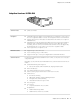
M10i Internet Router PIC Guide Fast Ethernet PICs Left: 4-Port Fast Ethernet PIC; Right: 8-Port Fast Ethernet PIC Left: 12-Port Fast Ethernet PIC; Right: VHDCI to RJ-21 cable Software release ■ JUNOS 6.1 and later Description ■ 4 or 12 100Base-TX ports; 8 100Base-FX ports ■ Power requirement: Hardware features Software features 44 ■ Fast Ethernet PICs ■ 4-port: 0.14 A @ 48 V (6.8 W) ■ 8-port: 0.26 A @ 48 V (12.5 W) ■ 12-port: 0.
Fast Ethernet PICs Cables and connectors 4-port PIC: ■ Connector: Two-pair, Category 5 unshielded twisted-pair connectivity through an RJ-45 connector ■ Pinout: MDI noncrossover 8-port PIC: ■ Connector: MT-RJ female ■ FX optical interface—see Table 8 on page 45 12-port PIC: ■ LEDs Connector: One very High Density Connector Interface (VHDCI) to RJ-21 cable that connects to an RJ-45 patch panel Status LED, one bicolor: ■ Off—PIC ports not enabled ■ Green—PIC is operating normally ■ Red—PIC h
M10i Internet Router PIC Guide Table 8: Optical Interface Support for Fast Ethernet PICs (continued) Optical Parameters FX interface for 8-Port Maximum distance 62.5/125 micrometer MMF: 1.
Gigabit Ethernet PIC with SFP Gigabit Ethernet PIC with SFP Software release ■ JUNOS 6.3 and later Description ■ One Gigabit Ethernet port ■ Power requirement: 0.15 A @ 48 V (7.
M10i Internet Router PIC Guide LEDs Status LED, one bicolor: ■ Off—PIC is not enabled ■ Green—PIC is operating normally ■ Red—PIC has an error or failure Port LEDs, one pair per port: ■ Link—If green, the port is online; if there is no light, the port is down ■ Activity—If flashing green, the port is receiving data; if there is no light, the port might be on but is not receiving data Table 9: Optical Interface Support for Gigabit Ethernet PICs with SFP Parameter 1000Base-SX 1000Base-LX 1000Ba
Gigabit Ethernet IQ PIC with SFP Gigabit Ethernet IQ PIC with SFP Software release ■ JUNOS 6.1 and later Description ■ One Gigabit Ethernet port ■ Power requirement: 0.46 A @ 48 V (22 W) ■ Intelligent queuing (IQ) PICs support fine-grained queuing per-logical interface. ■ High-performance throughput at speeds up to 1 Gbps ■ Full-duplex mode ■ Large MTUs of up to 9192 bytes ■ Optical diagnostics and related alarms (JUNOS Release 8.
M10i Internet Router PIC Guide LEDs ■ ■ Status LEDs, one tricolor: ■ Off—Not enabled ■ Green—Online with no alarms or failures ■ Amber—Online with alarms for remote failures ■ Red—Active with a local alarm; router has detected a failure Port LEDs, one per port: ■ Off—Port is down ■ Green—Link is established Table 10: Optical Interface Support for Gigabit Ethernet IQ PICs with SFP 50 ■ Parameter 1000Base-SX 1000Base-LX 1000Base-LH Optical interface Multimode Single-mode Single-mode
Gigabit Ethernet IQ2 PIC with SFP Gigabit Ethernet IQ2 PIC with SFP Software release Description Hardware features Software features ■ JUNOS 7.6R3 and later ■ Four Gigabit Ethernet ports ■ Power requirement: 0.
M10i Internet Router PIC Guide Cables and connectors ■ You can install any transceiver supported by the PIC. For information about installing and removing transceivers, see the PIC and Transceiver Installation Instructions. NOTE: Do not install SONET/SDH SFPs in the Gigabit Ethernet port. The port will not recognize the SFP.
Gigabit Ethernet IQ2 PIC with SFP Table 11: Optical Interface Support for Gigabit Ethernet IQ2 PICs with SFP (continued) Parameter 1000Base-SX 1000Base-LX 1000Base-LH Average launch power –9.5 through 0 dBm –11.
M10i Internet Router PIC Guide Link Services PIC Software release ■ JUNOS 6.1 and later Description ■ Power requirement: 0.
MultiServices 100 PIC MultiServices 100 PIC Software release ■ JUNOS 8.1 and later Description ■ Supports tunnel services. This feature is included with the PIC and does not require an individual license. ■ Individual licenses must be purchased for additional services. ■ Power requirement: 0.52 A @ 48 V (25 W) Hardware features ■ Active monitoring on up to 1.
M10i Internet Router PIC Guide Table 12: MultiServices PICs Software Features Supported by the M10i Router (continued) Stateful firewall with packet inspection: detects SYN attacks, ICMP and UDP floods, and ping of death attacks 8.1 Network Address Translation (NAT) for IP addresses 8.1 Port Address Translation (PAT) for port numbers 8.1 IP Security (IPSec) encryption 8.1 Active flow monitoring exports cflowd version 5 and version 8 records 8.
SONET/SDH OC3c/STM1 PIC SONET/SDH OC3c/STM1 PIC Software release ■ JUNOS 6.1 and later (Type 1) NOTE: Although the illustration shows a multimode PIC, both a multimode PIC and a single-mode intermediate reach PIC are supported. Description Hardware features Software features Cables and connectors ■ Four OC3 ports ■ Power requirement: 0.49 A @ 48 V (23.
M10i Internet Router PIC Guide Alarms, errors, and events ■ ■ SONET alarms: ■ Alarm indication signal—line (AIS-L) ■ Alarm indication signal—path (AIS-P) ■ Bit error rate signal degrade (BERR-SD) ■ Bit error rate signal fail (BERR-SF) ■ Bit interleaved parity (BIP) error B1 ■ Bit interleaved parity (BIP) error B2 ■ Bit interleaved parity (BIP) error B3 ■ Loss of frame (LOF) ■ Loss of pointer (LOP-P) ■ Loss of signal (LOS) ■ Far-end bit error: remote error indication—line (REI-L) (CV
SONET/SDH OC3c/STM1 PIC Table 13: Optical Interface Support for SONET/SDH OC3c/STM1 PICs (continued) Parameter Intermediate Reach Multimode Standard Telcordia GR-253 Multivendor agreement Maximum distance SMF cable: 9.3 miles/15 km MMF cable: 1.
M10i Internet Router PIC Guide SONET/SDH OC3c/STM1 PIC with SFP Software release ■ JUNOS 8.4 and later Description ■ Two OC3c ports ■ Power requirement: 0.
SONET/SDH OC3c/STM1 PIC with SFP Alarms, errors, and events ■ ■ SONET alarms: ■ Alarm indication signal—line (AIS-L) ■ Alarm indication signal—path (AIS-P) ■ Bit error rate signal degrade (BERR-SD) ■ Bit error rate signal fail (BERR-SF) ■ Bit interleaved parity (BIP) error B1 ■ Bit interleaved parity (BIP) error B2 ■ Bit interleaved parity (BIP) error B3 ■ Loss of frame (LOF) ■ Loss of pointer (LOP-P) ■ Loss of signal (LOS) ■ Far-end bit error: remote error indication—line (REI-L) (
M10i Internet Router PIC Guide Table 14: Optical Interface Support for SONET/SDH OC3c/STM1 PICs with SFP (continued) Multimode Intermediate Reach (IR-1) Long Reach (LR-1) Transceiver type SFP SFP SFP Maximum distance MMF cable: 1.2 miles/2 km SMF cable: 9.3 miles/15 km SMF cable: 24.
SONET/SDH OC3/STM1 (Multi-Rate) PIC with SFP SONET/SDH OC3/STM1 (Multi-Rate) PIC with SFP Software release ■ JUNOS 8.4 and later Description ■ Rate-selectable using one of the following rates: Hardware features Software features Cables and connectors ■ 1-port OC12 ■ 1-port OC12c ■ 4-port OC3c ■ Power requirement: 0.
M10i Internet Router PIC Guide LEDs One tricolor per port: Alarms, errors, and events ■ Off—Not enabled ■ Green—Online with no alarms or failures ■ Amber—Online with alarms for remote failures ■ Red—Active with a local alarm; router has detected a failure ■ SONET alarms: ■ 64 ■ ■ Alarm indication signal—line (AIS-L) ■ Alarm indication signal—path (AIS-P) ■ Bit error rate signal degrade (BERR-SD) ■ Bit error rate signal fail (BERR-SF) ■ Bit interleaved parity (BIP) error B1 ■ Bit
SONET/SDH OC3/STM1 (Multi-Rate) PIC with SFP Table 15: Optical Interface Support for SONET/SDH OC3/STM1 (Multi-Rate) PICs with SFP Configured at an OC3/STM1 Rate Parameter Multimode Intermediate Reach (IR-1) Long Reach (LR-1) Transceiver model number SFP-OC3-SR SFP-OC3-IR SFP-OC3-LR Optical interface Multimode Single-mode Single-mode Transceiver type SFP SFP SFP Maximum distance MMF cable: 1.2 miles/2 km SMF cable: 9.3 miles/15 km SMF cable: 24.
M10i Internet Router PIC Guide SONET/SDH OC12c/STM4 PIC Software release ■ JUNOS 6.1 and later Description ■ One port ■ Power requirement: 0.23 A @ 48 V (10.
SONET/SDH OC12c/STM4 PIC Alarms, errors, and events ■ ■ SONET alarms: ■ Alarm indication signal—line (AIS-L) ■ Alarm indication signal—path (AIS-P) ■ Bit error rate signal degrade (BERR-SD) ■ Bit error rate signal fail (BERR-SF) ■ Bit interleaved parity (BIP) error B1 ■ Bit interleaved parity (BIP) error B2 ■ Bit interleaved parity (BIP) error B3 ■ Loss of frame (LOF) ■ Loss of pointer (LOP-P) ■ Loss of signal (LOS) ■ Far-end bit error: remote error indication—line (REI-L) (CV-LFE)
M10i Internet Router PIC Guide Table 17: Optical Interface Support for SONET/SDH OC12c/STM4 PICs (continued) Parameter Intermediate Reach Multimode Standard Telcordia GR-253 Multivendor agreement Maximum distance SMF cable: 9.3 miles/15 km MMF cable: 546.
SONET/SDH OC12/STM4 (Multi-Rate) PIC with SFP SONET/SDH OC12/STM4 (Multi-Rate) PIC with SFP Software release ■ JUNOS 8.4 and later Description ■ Rate-selectable using one of the following rates: Hardware features Software features Cables and connectors ■ 1-port OC3 ■ 1-port OC12 ■ 1-port OC12c ■ Power requirement: 0.20 A @ 48 V (9.
M10i Internet Router PIC Guide LEDs One tricolor per port: Alarms, errors, and events ■ Off—Not enabled ■ Green—Online with no alarms or failures ■ Amber—Online with alarms for remote failures ■ Red—Active with a local alarm; router has detected a failure ■ SONET alarms: ■ 70 ■ ■ Alarm indication signal—line (AIS-L) ■ Alarm indication signal—path (AIS-P) ■ Bit error rate signal degrade (BERR-SD) ■ Bit error rate signal fail (BERR-SF) ■ Bit interleaved parity (BIP) error B1 ■ Bit
SONET/SDH OC12/STM4 (Multi-Rate) PIC with SFP Table 18: Optical Interface Support for SONET/SDH OC12/STM4 (Multi-Rate) PICs with SFP Configured at an OC3/STM1 Rate Parameter Multimode Intermediate Reach (IR-1) Long Reach (LR-1) Transceiver model number SFP-OC3-SR SFP-OC3-IR SFP-OC3-LR Optical interface Multimode Single-mode Single-mode Transceiver type SFP SFP SFP Maximum distance MMF cable: 1.2 miles/2 km SMF cable: 9.3 miles/15 km SMF cable: 24.
M10i Internet Router PIC Guide SONET/SDH OC48c/STM16 PIC with SFP Software release ■ JUNOS 6.4 and later Description ■ One OC48 port ■ Power requirement: 0.86 A @ 48 V (41.
SONET/SDH OC48c/STM16 PIC with SFP LEDs Alarms, errors, and events One tricolor per port: ■ Off—Not enabled ■ Green—Online with no alarms or failures ■ Amber—Online with alarms for remote failures ■ Red—Active with a local alarm; router has detected a failure ■ SONET alarms: ■ ■ Alarm indication signal—line (AIS-L) ■ Alarm indication signal—path (AIS-P) ■ Bit error rate signal degrade (BERR-SD) ■ Bit error rate signal fail (BERR-SF) ■ Bit interleaved parity (BIP) error B1 ■ Bit inte
M10i Internet Router PIC Guide Table 20: Optical Interface Support for SONET/SDH OC48c/STM16 PICs with SFP Parameter Short Reach (SR) Intermediate Reach (IR) Long Reach (LR) Optical interface Single-mode Single-mode Single-mode; compatible with 1550-nm single-mode LR Transceiver type SFP SFP SFP Maximum distance SMF cable: 1.24 miles/2 km SMF cable: 9.3 miles/15 km SMF cable: 49.71 miles/80 km Standard Telcordia GR-253 Telcordia GR-253 Telcordia GR-253—L-16.
T1 PIC T1 PIC Software release ■ JUNOS 6.1 and later Description ■ Four T1 ports ■ Power requirement: 0.08 A @ 48 V (3.7 W) ■ Supports clear channel T1 per port (1.
M10i Internet Router PIC Guide Tunnel Services PIC Software release ■ JUNOS 6.1 and later Description ■ Power requirement: 0.07 A @ 48 V (3.4 W) Hardware features ■ Loopback function that encapsulates and de-encapsulates packets ■ SONET/SDH OC12/STM4 tunneling bandwidth Software features LEDs 76 ■ For a list of the software features available for services PICs, see the JUNOS Services Interfaces Configuration Guide.
Appendix A High Availability Features High availability features include Routing Engine redundancy, graceful Routing Engine switchover (GRES), nonstop bridging, nonstop active routing, graceful restart for routing protocols, Virtual Router Redundancy Protocol (VRRP), and unified in-service software upgrade (ISSU). Some high availability features are not supported by all platforms and all PICs.
Copyright © 2008, Juniper Networks, Inc. All rights reserved. Juniper Networks, the Juniper Networks logo, NetScreen, and ScreenOS are registered trademarks of Juniper Networks, Inc. in the United States and other countries. JUNOS and JUNOSe are trademarks of Juniper Networks, Inc. All other trademarks, service marks, registered trademarks, or registered service marks are the property of their respective owners. Juniper Networks assumes no responsibility for any inaccuracies in this document.