
- Juniper Router Hardware Guide


Site Preparation
Checklist
the power to bring it within the allowable range; for short lengths of fiber, with fiber and
connector loss close to zero, an attenuator of 5 to 10 dB should be sufficient.
For specifications of minimum and maximum input level (receiver sensitivity and receiver
saturation) and minimum and maximum output level (average launch power) for the
SONET/SDH PIC
s supported on the M5 and M10 routers, see the M5 and M10 Internet
Routers PIC Guide.
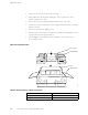
Cable Specifications for Routing E ngine Management Interfaces
For management and service operations, you c onnect the Routing Engine to an external
console or management network through ports on the craft interface. For information about
the ports, se
e “Routing Engine Interface Ports and Status Indicators” on page 15.
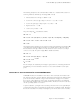
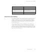
Table 13 lists the specifications for the cables that connect to management ports.
Table 13: Cable Specifications for Routing Engine Management Interfaces
Port
Cable
Specification
Cable/Wire
Supplied
Maximum
Length
Router
Receptacle
Routing Engine
console or
auxiliary
interface
RS-232 (EIA-232)
serial
One 6-ft (1.83-m)
length with
DB-9/DB-9
connectors
6 ft (1.83 m) DB-9 male
Routing Engine
Ethernet
interface
Category 5
cable
or equivalent
suitable f
or
100BaseT
operation
One 15-ft (
4.57-m)
length with
RJ-45/RJ-
45
connectors
328 ft (100
m)
RJ-45
autosensing
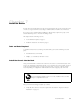
Site Preparation Checklist
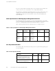
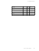
The checkl
ist in Table 14 summarizes the tasks you need to perform when preparing a site
forrouterinstallation.
Table 14: Site Preparation Checklist
Item or Task
Performed
By Date Notes
Verify t
hat environmental factors such
as temperature and humidity do not
exceed r
outer tolerances (see “Router
Environmental To lerances” on page 40).
Measure distance between external power
sources and router installation site.
52 M5 and M10 Internet Routers Hardware Guide