
Internet Router Hardware Guide


Preparing for Router Installation
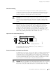
Interface Panel (CIP). You can also connect the router to external alarm-reporting
devices through the alarm relay contacts on the CIP. (For more information,
see Connector Interface Panel (CIP) on page 32.)
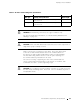
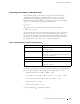
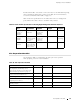
Table 19 lists the specifications for the cables that connect to management
ports and the wires that connect to the alarm relay contacts.
Table 19: Cable and Wire Specifications for Routing Engine Management and Alarm Interfaces
Port
Cable
Specificati
on
Cable/Wire
Supplied
Maximum
Length
Router
Receptacle
Routing Engine
console or
auxiliary
interface
RS-232 (EIA-232)
serial cable
One 6-ft (1.83-m)
length with
DB-9/DB-9
connectors
6 ft (1.83 m) DB-9 male
Routing Engine
Ethernet
interface
Category 5 cable or
equivalent suitable
for 1 00BaseT
operation
One 15-ft (4.57-m)
length with
RJ-45/RJ-45
connectors
328 ft (100 m)
RJ-45
autosensing
Alarm relay
contacts
Wire with gauge
between 24-AWG
and 12-AWG (0.20
and 3.33 mm
2
)
No None
—
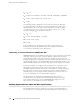
Site Preparation C hecklist
The checklist in Table 20 summarizes the tasks you need to perform
when preparing a site for router installation.
Table 20: Site Preparation Checklist
Item or Task Performed By Date Notes
Verify that environmental factors such
as temperature and humidity do not
exceed router tolerances (see Routing Node
Environmental Specifications on page 62).
Measure distance between external pow er
sources and router installation site.
Select the type of rack or cabinet.
Plan rack or cabinet location, including
required space clearances.
If a rack is used, secure rack to floor and
building structur e.
Acquire cables and connectors.
Site Preparation Checklist 75