
Internet Router Hardware Guide


M160 Internet Router Hardware Guide
P
M
=P
B
–LL
P
M
=13dB–2km(1.0dB/km)–5(0.5dB)–2(0.5dB)–0.5dB[HOL]–1dB[CRM]
P
M
=13dB–2dB–2.5dB–1dB–0.5dB–1dB
P
M
=6dB
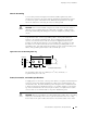
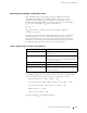
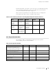
The following sample calcu lat ion for an 8 km-long single-mode link with
a power budget (
P
B
) of 13 dB uses the estimated values from Table 18 to
calculate link loss (
LL) as the sum of fiber attenuation (8 km @ 0.5 dB/km,
or 4 dB) and loss for seven connectors (0.5 dB per connector, or 3.5 dB).
The power margin (
P
M
) is calculated as follows:
P
M
=P
B
–LL
P
M
=13dB–8km(0.5dB/km)–7(0.5dB)
P
M
=13dB–4dB–3.5dB
P
M
=5.5dB
In both examples, the calculated power margin is greater than zero,
indicating that the link has sufficient power for transmission and does
not exceed the maximum receiver input power.
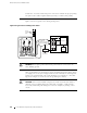
Attenuating to Prevent Satu ration at SONET/SDH P ICs
SONET/SDH interfaces in the different reach classes—short reach (SR), intermediate
reach (IR), and long reach (LR)—generate different output power levels and
tolerate different input power levels. Interfaces that have a longer reach can
transmit enough power to saturate the receivers on PICs that have a shorter reach.
Specifically, LR interfaces can saturate IR PICs, and both IR and LR interfaces can
saturate SR PICs. Interfaces in the same reach class can also saturate one another.
To prevent saturation, you might need to attenuate po wer at the PIC receiver,
particularly if you know that it has a shorter reach than the interface that is
sending the signal. Determine the amount of attenuation needed by measuring
the power level at each receiver. Attenuate the power to bring it within the
allowable r ange; f o r short lengths of fiber, with fiber and connector loss close
tozero,anattenuatorof5to10dBshouldbesufficient.
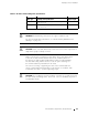
Forspecificationsofminimumandmaximuminputlevel(receiver
sensitivity and receiver saturation) and minimum and maximum output
level (average launch power) for the SONET/SDH PICs supported on the
M160 router, see the M160 Internet Router PIC Guide.
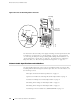
Routing Engine Interface Cable and Wire Specifications
For management and service operations, you connect the Routing Engine to
an external console or management network through ports on the Connector
74 Routing Engine Interface Cable and Wire Specifications