
Internet Router Hardware Guide


Preparing for Router Installation
Calculating Power Margin for Fiber-Optic Cable
After calculating a link’s power budget (using the equation described in
“Calculating Power B udget for Fiber-Optic Cable” on page 72), you can
calculate the power margin (
P
M
),whichrepresentstheamountofpower
available after subtracting attenuation or link loss (
LL) from the power budget
(
P
B
).Aworst-caseestimateofP
M
assumes maximum LL:
P
M
=P
B
–LL
A P
M
greater than zero indicates that the power budget is sufficient
to operate the receiver.
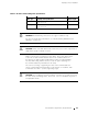
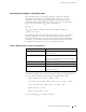
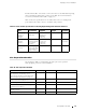
Factors that can cause link loss include higher-order mode losses, modal and
chromatic dispersion, connectors, splices, and fiber attenuation. Table 18
lists an estimated amount of loss for the factors used in the following sample
calculations. For information about the actual amount of signal loss caused
by equipment and other factors, refer to vendor documentation.
Table 18: Estimated Values for Factors Causing Link Loss
Link-Loss Factor Estimated Link-Loss Value
Higher-order mode losses Single-mode—None
Multimode—0.5 dB
Modal and chromatic dispersion Single-mode—None
Multimode—None, if product of bandwidth and distance
is less than 500 MHz–km
Connector
0.5 dB
Splice 0.5 dB
Fiber attenuation Single-mode—0.5 dB/km
Multimode—1 dB/km
The following example uses the estimated values in Table 18 to calculate link loss
(
LL)fora2km-longmultimodelinkwithapowerbudget(P
B
)of13dB:
Fiber attenuation for 2 km @ 1.0 dB/km= 2 dB
Loss for five connectors @ 0.5 dB per connector = 5(0.5 dB) = 2.5 dB
Loss for two splices @ 0.5 dB per splice =2(0.5 dB) = 1 dB
Higher-order loss = 0.5 dB
Clock recovery module = 1 dB
The power margin (
P
M
) is calculated as follows:
Network Cable Specifications and Guidelines 73