
Internet Router Hardware Guide

Preparing for Router Installation
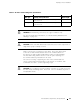
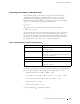
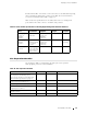
Table 17: DC Power and Grounding Cable Specifications
Cable T ype Quantity and S
pecification
Maximum
Equal Length
Power
Eight 4-AWG (16 mm
2
) wires, minimum, or as permitted
by the local code
None
Grounding One 8-AWG (8.4 mm
2
) wire, minimum, or as permitted
by the local code
None
WARNING: For field-wiring connections, use copper conductors only.
For other electrical safety information, see “Electrical Safety Guidelines and
Warnings” on page 227.
CAUTION: Power cords and cables must not block access to router components or
drape where people could t rip on them.
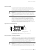
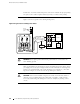
Figure 30 shows how to attach the power cables. The power cables attach
to the 1/4–20 UNC terminal studs located on the circuit breaker box—
the input set of studs is labeled
–48V andthereturnsetislabeledRTN(+).
Thenutsandlockingwashersusedtosecurethepowercablelugson
the terminal studs are preinstalled on the studs.
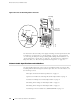
The tool for loosening or tightening the nuts on the terminal studs is a
7/16-in. hexagonal-head external drive socket wrench, or nut driver, with
a minimum of 30 lb-in. (3.5 Nm) tightening torque.
CAUTION: Do not substitute a metric nut driver or wrench. A tool that does not fit
thenutsexactlycandamagethem.Ifa7/16-in.toolisnotavailable,usepliersor
an adjustable wrench.
Power Guidelines, Requirements, and Specifications 69