
Internet Router Hardware Guide


M160 Internet Router Hardware Guide
breaker box. You must ensure that power connections maintain the proper polarity.
The power source cables might be labeled
(+) and (–) to indicate their polarity.
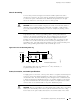
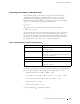
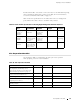
Figure 29 shows a typical source cabling arrangement.
Figure 29: Typical Source Cabling to the Router
Chassis
grounding
points
Ground
window
AC
Central
office ground
Plant
controls
Rectifiers
Battery plant
Batteries
1975
Central
office ground
Central office
primary & secondary
DC power distribution
WARNING: Power plant ground and chassis ground must be connected to the
same building ground.
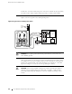
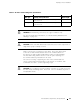
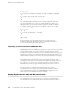
Table 17 summarizes the specifications for the grounding and power cables, which
you supply. The accessory bo x shipped with the router includes the cable lugs that
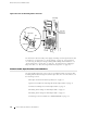
attach to the terminal studs of the circuit breaker box (see Figure 28). (The cable
lug shown in Figure 28 is also used for the grounding the chassis.)
CAUTION: Before router installation begins, a licensed electrician must attach a
cable lug to the grounding and power cables that you supply. A cable with an
incorrectly attached lug can damage the router (for example, by causing a short
circuit).
68 Power Guidelines, Requirements, and Specifications