
Internet Router Hardware Guide


M160 Internet Router Hardware Guide
Connection to Building Structure
Always secure the rack to the structure of the building. If your geographical
area is subject to earthquakes, bolt the rack to the floor. For maximum
stability, also secure the rack to ceiling brackets . For more information, see
“Rack-Mounting Requirements and Warnings” on page 240.
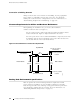
Clearance Requirements for Airflow and Hardwa re Maintenance
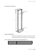
When planning the installation site, you need to allow sufficient
clearance around the rack (see Figure 27):
For the cooling system to function properly, the airflow around the chassis
must be unrestricted. Figure 20 depicts the airflow in the router.
For service personnel to remove and install hardware components, there must
be adequate space at the front and back of the router. Allow at least 24 in.
(61cm)bothinfrontoftherouterandbehindit.
Figure 27: Chassis Dimensions and Clearance Requirements
Rear of chassis
Front of chassis
24 in. (61 cm) clearance
for maintenance
Center rack-mount ears
17.5 in.
(44.5 cm)
29 in.
(73.6 cm)
24 in. (61 cm) clearance
for maintenance
6 in. (15.2 cm) clearance
for airflow
6 in. (15.2 cm) clearance
for airflow
1169
19 in.
(48.3 cm)
Top down view
19 in.
(48.3 cm)
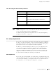
Routing Node Environmental Specifications
Table 15 specifies the environmental specifications required for normal
router operation. In addition, the site should be as dust-free as possible.
Dust can clog air intake vents, reducing cooling system efficiency. Check the
vents frequently, cleaning them as necessary. For more information, see
“Maintaining Hardware Components” on page 127.
62 Routing Node Environmental Specifications