
Internet Router Hardware Guide


Hardware Component Over view
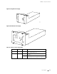
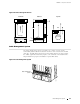
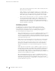
Figure 20: Airflow through the Chassis
Side view
Front
Rear
Front view
Top view
Impeller
Impeller
(upper front)
Impeller
Card cage
Fan tray
1170
Front
Rear
(upper rear)
Air intake cover
Impeller
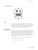
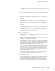
Cable Management System
The cable management system (see Figure 21) consists of a row of nine
semicircular plastic bobbins mounted on the front of the router below the FPC
card cage. The PIC cables pass between the bobbins and into the tray, k eeping
the cables organized and securely in place. T he curvature of the bobbins also
helps maintain the proper bend radius for optical PIC cables.
Figure 21: Cable Management System
1938
Cable management
system
Cable Management System 41