
Internet Router Hardware Guide

M160 Internet Router Hardware Guide
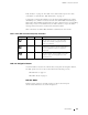
The ports with the indicated label in each set function as follows:
ETHERNET—Connects the Routing Engine through an Ethernet connection to a
management LAN (or any other device that plugs into an Ethernet connection)
for out-of-band management. The port uses an autosensing RJ-45 connector to
support b oth 10- and 100-Mbps connections. Two small LEDs on the left edge
of the port indicate the connection in use: the LED labeled
ETHERNET lights
yellow or green for a 10-Mbps or 100-Mbps connection, and the LED labeled
ACT lights green when traffic is passing through the port.
CONSOLE—Connects the Routing Engine to a system console through an
RS-232 (EIA-232) serial cable.
AUXILIARY— Connects the Routing Engine to a laptop, modem, or other
auxiliary device through an RS-232 (EIA-232) serial cable.
For information about the pinouts for the connectors, see “Cable
Connector Pinouts” on page 269.
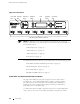
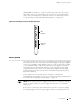
Figure 15 shows the ports that connect to the Routing Engine installed in slot
RE 0.
The arrangement of ports for the Routing Engine installed in slot RE 1 is the same.
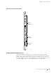
Figure 15: Routing Engine Interface Ports for Hos t Module 0
Ethernet
LEDs
Ethernet port
Console port
Auxiliary port
1236
HOST
0
YEL=10Mb
GRN=100Mb
ACT
ETHERNET
CONSOLE
AUXILIARY
BITS Input Ports
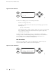
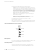
In the center of the CIP are two ports labeled BITS A and BITS B (see Figure 16). The
router does not support BITS input, so these ports do not function.
Alarm Relay Contacts
At the bottom of the CIP are two relay contacts for connecting the router to
external alarm-reporting devices, the upper labeled
RED ALARM and the lower
34 Connector Interface Panel (CIP)