
Internet Router Hardware Guide

Hardware Component Over view
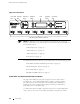
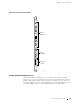
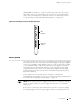
Figure 14: Connector Interface Panel
HOST
0
YEL=10Mb
GRN=100Mb
ACT
ETHERNET
ETHERNET
CONSOLE
CONSOLE
AUXILIARY
AUXILIARY
HOST
1
YEL=10Mb
GRN=100Mb
ACT
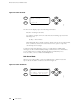
BITS A
BITS B
LINK
RED ALARM
YELLOW
ALARM
LINK
1204
Alarm relay
contacts
BITS
input ports
Routing
Engine ports
NC
C
NO
NC
C
NO
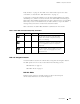
Routing Engine Management Ports
On the upper half of the CIP are two sets of ports for connecting the Routing
Engines to one or more external devices on which system administrators can issue
JUNOS command-line interfa ce (CLI) commands to m anage the router. The set of
ports labeled
HOST0 connects to the Routing Engine in the slot labeled RE 0,andthe
set labeled
HOST1 connects to the Routing Engine in the slot labeled RE 1.
Connector Interface Panel (CIP) 33