
Internet Router Hardware Guide

Hardware Component Over view
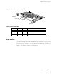
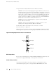
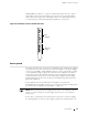
The lines in the display report the f ollowing information:
First line—Routing node name.
Second line—Number of active alarms.
Third and fourth lines—Individual alarm messages, with the most severe
condition shown first. The prefix on each line indicates whether the alarm is a
red (
R) or yellow (Y) alarm.
For a list of alarm messages that can appear on the LCD, see “Chassis
and Interface Alarm Messages” on page 209.
Host Modul e LEDs
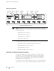
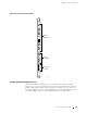
Attheupperrightcornerofthecraftinterface(seeFigure11)aretwosetsofLEDs
that indicate host module status: the set labeled
HOST0 reports the status of the
Routing Engine in slot
RE 0 and MCS in slot MCS 0, and the set labeled HOST1 reports
thestatusoftheRoutingEngineinslot
RE 1 and the MCS in slot MCS 1.Eachset
includes three LEDs—a green one labeled
MASTER, another green one labeled
ONLINE, and a red one labeled OFFLINE. Table 10 describes the LED states.
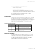
Table 10: States for Host Module LEDs
Label Color State Description
MASTER
Green
On steadily Host module is functioning as master.
On steadily Host module components (Routing Engine and
MCS) are installed and functioning normally.
ONLINE
Green
Blinking Host module is starting up.
OFFLINE Red On steadily One or both host module components ar e not
installed or have failed.
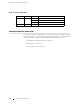
FPC LEDs a
nd Offline Button
The LEDS and offline button for each FPC are located d irectly above it on the
craft interface, as shown in Figure 11. The red LED labeled
FAIL and the green
LED labeled
OK indicate FPC status, as described in Table 11.
The offline button, labeled with the FPC slot number (for example,
FPC2),
prepares the FPC for removal from the router when pressed.
Craft Interface 31