
Internet Router Hardware Guide

M160 Internet Router Hardware Guide
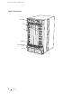
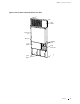
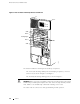
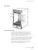
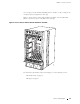
FPC Components
An FPC has the following components:
FPC card carrier—Houses the ASICs, connectors, and p rocessor subsystem.
Four I/O Manager ASICs—Parse Layer 2 and Layer 3 data and perform
encapsulation and segmentation. The I/O Manager ASICs divide incoming
packets into 64-byte data cells for easier processing, and reassemble the cells
for each packet after the forwarding decision is made for it. Enhanced FPCs
have I/O Manager ASICs capable of enhanced quality of service.
Two Packet Director ASICs—Transfer packets between the PICs and the I/O
Manager ASICs: one directs incoming packets from the PICs to the I/O
Manager ASICs, while the second directs outgoing packets from the I/O
Manager ASICs to the PICs.
Eight identical synchronous DRAM (SDRAM) dual inline memory modules
(DIMMs)—Form the memory pool shared with the other FPCs installed
in the router.
Parity-protectedsynchronousSRAM(SSRAM)—Storesdatastructuresused
by the I/O Manager ASICs.
Processor subsystem—Manages packet handling in the FPC and
communication with the SFM. It is a PowerPC 603e-based CPU with
parity-protected DRAM.
EEPROM—Stores the serial number and revision level of the FPC.
Two LEDs—Indicate FPC status. The LED labeled OK is green and the one
labeled
FAIL is red. The LEDs for each FPC are located on the router craft
interface. For more information, see “FPC LEDs and Offline Button” on
page 31.
Offline b utton—Prepares the FPC for removal from the router when pressed.
Like the LEDs, an offline button is located on the craft interface. For more
information, see “FPC LEDs and Offline Button” on page 31.
Four PIC offline buttons (on FPC1 only)—Prepare each corresponding PIC
for removal from the FPC.
Ejector lev ers—Control the locking system that secures the FPC in the card
cage.
NOTE: For specific information about FPC components (for example, the amount of
memory available), issue the
show chassis fpc command.
16 Packet Forwarding Engine