
Internet Router Hardware Guide


Appendix C
Cable Connector Pinouts
This chapter describes the pinouts for the following cable connectors:
RJ-45 Connector Pinouts for the Routing Engine ETHERNET Port on page 269
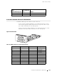
DB-9 Connector Pinouts for the Routing Engine AUXILIARY and CONSOLE
Ports on page 270
RJ-48 Cable Pinouts for E1 and T 1 PICs on page 270
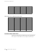
X.21 and V.35 Cable Pinouts for EIA-530 PIC on page 273
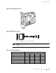
Fast Ethernet 48-port Cable Pinouts on page 274
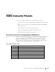
RJ-45 Connector Pinouts for the Routing Engine ETHERNET Port
The port on the CIP labeled ETHERNET is an autosensing 10/100-Mbps Ethernet
RJ-45 receptacle that accepts an Ethernet cable for connecting the Routing
Engine to a management LAN (or other device that supports out-of-band
management). For more information, see “Routing Engine Management Ports”
on page 33. Table 28 describes the RJ-45 connector pinout.
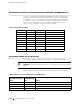
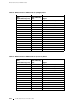
Table 28: RJ-45 Connector Pinout
Pin Signal
1TX+
2TX-
3
RX+
4
Termination network
5
Termination network
6
RX-
7
Termination network
8
Termination network
RJ-45 Connector Pinouts for the Routing Engine ETHERNET Port 269