
Internet Router Hardware Guide

Replacing Hardware Components
WARNING: Y ou must power off the router before removing or installing a fuse.
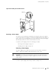
1. A tt ach an electrostatic discharge (ESD) grounding strap to your bare wrist and
connect the strap to one of the ESD points on the chassis. Make sure t he router
is attached to a proper earth ground. For more information about ESD, see
“Preventing Electrostatic Discharge Damage” on page 226.
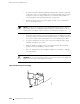
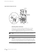
2. Remove the rear lower impeller a ssembly by loosening the thumbscrew at
each corner of the impeller cover and sliding the impeller assembly out of the
chassis. For complete instructions, see “Removing the Rear Lower Impeller
Assembly” on page 155.
3. Determine which fuse has blown. The amber LED under the fuse lights and the
indicator bulb b ecomes visible through the clear cover on the fuse.
4. Power off the router as described in or “Disconnecting Power from the Router”
on page 200.
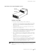
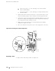
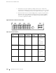
5. Grasp the blown fuse by the edges and rock it in its slot until it comes loose and
disconnects. Rock up and down for a vertically oriented fuse (in the groups
labeled
J241 through J243 inFigure106)andsidetosideforahorizontally
oriented fuse (in the group labeled
J240). If the cover slips off the fuse, snap
the cover back into place and begin again.
NOTE: We recommend you use an insulated fuse r emov al tool to remove fuses.
6. Remove the appropriate spare fuse from the group of fuses labeled J244 in
Figure 106. (The labels shown in the figure do not appear on the actual
fuses—the clear cover on every fuse reads
BUSS GMT-X—but a table on the
midplanebelowthefuseboxdisplaysthesameinformation.) Verifythat
the spare has the same rating and color coding as the fuse it is replacing,
as specified in Table 25. To see the indicator bulb and printed rating, look
atthefusefromtheside.
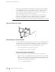
7. For a vertically oriented fuse, orient the replacement fuse over the slot so
that the text on the fuse cover (
BUSS GMT-X) reads from bottom to top. For a
horizontally oriented fuse, orient the replacement fuse over the slot so that the
text on the fuse cover is upside down.
8. Press the new fuse into the slot.
9. Power on the router as described in “Powering On the Router” on page 119.
10. Verify that the amber LED under the replacement fuse is no longer lit.
Replacing Power System Components 205