
Internet Router Hardware Guide

Replacing Hardware Components
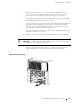
3. Remove the rear component cover by loosening the thumbscrew at each
corner of the cover and pulling it straight off the chassis. For complete
instructions, see “Removing the Rear Component Cover” o n page 86.
4. Press and hold the offline button on the PCG faceplate until the amber LED
labeled
FAIL lights, which takes about 3 seconds.
(Keep in mind that if you are removing the master PCG, forwarding halts while
the Packet Forwarding Engine resets so that t he components start using
the clock signal from the other PCG, which becomes the master. For more
information, see “Replacing a PCG” on page 176.)
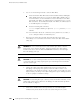
5. Loosen the thumbscrew at the lower right corner of the PCG faceplate , using
a Phillips screwdriver if necessary.
6. Grasp the thumbscrew and slide the PCG about halfway out of the chassis.
CAUTION: Be careful to slide the PCG straight out of the chassis to avoid bending
any of the pins on the underside of the board.
7. Place one hand under the PCG to support it, slide it completely out of the
chassis, and place it on the antistatic mat or in the electrostatic bag.
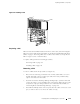
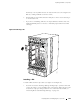
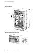
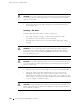
Figure 90: Removing a PCG
1929
PCG 0
SFM 0
SFM 1
MCS 0
RE 0
RE 1
MCS 1
PCG 1
Replacing Packet Forwarding Engine Components 177