
Internet Router Hardware Guide

M160 Internet Router Hardware Guide
1. A tt ach an electrostatic discharge (ESD) grounding strap to your bare wrist and
connect the strap to one of the ESD points on the chassis. Make sure t he router
is attached to a proper earth ground. For more information about ESD, see
“Preventing Electrostatic Discharge Damage” on page 226.
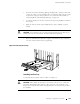
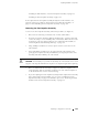
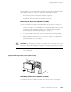
2. Grasp the sides of the fan tray and align the rear of the tray with the guides
inside the chassis.
3. Slidethefantrayallthewayintothechassis.
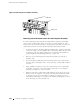
4. Tighten t he thumbscrew at each end of the cable management system.
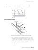
5. Rearrange the PIC cables in the cable management system. For more
information about proper cable arrangement, see “Maintaining PICs and
PIC Cables” on page 134.
Figure 70: Installing the Fan Tray
1937
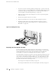
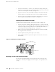
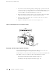
Replacing the Fro nt Impeller Assembly
The front impeller assembly, which includes the craft interface, is located at the
front of the chassis above the FPC card cage, as shown in Figure 1. The assembly
weighs approximately 14.5 lb (6.6 kg). The assembly is hot-removable and
hot-insertable, as described in Field-Replaceable Units (FRUs) on page 4.
The craft interface is attached to the front of the front impeller assembly. If you are
removing the front impeller assembly to replace it and the replacement assembly
does not have a craft interface already installed on it, you must transfer the craft
interface from the remov ed assembly to the replacement assembly. Perform the
procedures described in the following sections:
Removing the Front Impeller Assembly on page 151
Removing the Craft Interface from the Front Impeller Assembly on page 152
150 R eplacing Cooling System Com ponents