
Internet Router Hardware Guide

Replacing Hardware Components
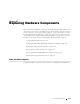
Replacing Connections to Ro utin g Engine In terface Ports
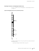
TheportsontheCIPconnecttheRoutingEnginetoexternalmanagementdevices
(see Figure 66).
Figure 66: Routing Engine Interface Ports and Alarm Relay Contacts
HOST
0
YEL=10Mb
GRN=100Mb
ACT
ETHERNET
ETHERNET
CONSOLE
CONSOLE
AUXILIARY
AUXILIARY
HOST
1
YEL=10Mb
GRN=100Mb
ACT
BITS A
BITS B
LINK
RED ALARM
YELLOW
ALARM
LINK
1204
Alarm relay
contacts
BITS
input ports
Routing
Engine ports
NC
C
NO
NC
C
NO
To replace the cables that connect to the p orts, perform the procedures described in
the following sections:
Replacing the Management Ethernet Cable on page 146
Replacing the CIP and Routing Engine I nterface Port Cables 145