
Internet Router Hardware Guide

Installing the Router without a Mechanical Lift
1. A tt ach an electrostatic discharge (ESD) grounding strap to your bare wrist and
connect the strap to one of the ESD points on the chassis. Make sure t he router
is attached to a proper earth ground. For more information about ESD, see
“Preventing Electrostatic Discharge Damage” on page 226.
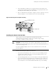
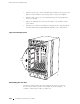
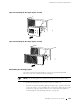
2. Grasp the sides of the fan tray and align the rear of the tray with the guides
inside the chassis.
3. Slidethefantrayallthewayintothechassis.
4. Tighten t he thumbscrew at each end of the cable management system.
Figure 47: Reinstalling the Fan Tray
1937
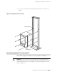
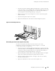
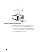
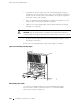
Reinstal ling the Rear Lower Impeller Asse mbly
The rear lower impeller assembly is located to the left of the circuit
breaker box on the rear of the chassis, as shown in Figure 2. To reinstall
it, follow this procedure (see Figure 48):
1. A tt ach an electrostatic discharge (ESD) grounding strap to your bare wrist and
connect the strap to one of the ESD points on the chassis. Make sure t he router
is attached to a proper earth ground. For more information about ESD, see
“Preventing Electrostatic Discharge Damage” on page 226.
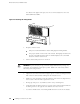
2. Orient the impeller so that the label is on the top. Align the rails on the upper
edges of the impeller assembly with the guides inside the chassis.
3. Pushtheimpellerassemblyupandtotherighttostartitintothechassis,
then slide it all the wa y in.
4. Tighten the thumbscrew at each corner of the impeller cover.
Reinstalling Components into the Chassis 103