
Internet Router Hardware Guide

Installing the Router without a Mechanical Lift
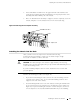
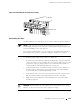
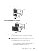
Figure 45: Reinstalling the Front Impeller Assembly
1216
R
Captive screw
Reinstalling the FPCs
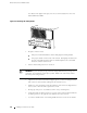
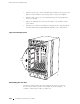
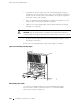
TheFPCsinstallintothecardcageatthefrontofthechassis,asshowninFigure1.
NOTE: To help you work systematically, the following procedure directs you to
reinstallFPCsstartingattheleftsideofthecardcageandworkingtowardtheright.
You can install FPCs in any order, however.
Be sure there is a blank panel over every empty slot. The blank panels must be in
place during router operation to guarantee adequate circulation of cooling air.
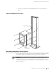
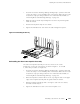
To reinstall the FPCs, follow this procedure (see Figure 46):
1. A tt ach an electrostatic discharge (ESD) grounding strap to your bare wrist and
connect the strap to one of the ESD points on the chassis. Make sure t he router
is attached to a proper earth ground. For more information about ESD, see
“Preventing Electrostatic Discharge Damage” on page 226.
2. Locate the leftmost slot in the FPC card cage on the fro nt of the chassis. It is
directly below the offline button on the craft interface that is labeled
FPC0.
Locate the FPC that you labeled
FPC0 during removal.
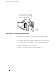
3. Verify that the ends of the ejector le vers, which are located at each end of the
FPC, are pushed outward, nearly perpendicular to the face of the FPC.
4. GraspthefrontoftheFPCwithonehandandplacetheotherhandunder
the FPC to support it.
CAUTION: WhentheFPCisoutofthechassis,donotholditbytheejectorlevers,
bus bars, or edge connectors. They cannot support its weight.
Reinstalling Components into the Chassis 101