
Internet Router Hardware Guide

M160 Internet Router Hardware Guide
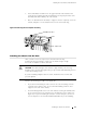
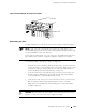
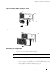
the chassis in an upper rack space, use the set of holes adjacent to the slots
labeled
SFM 2 and SFM 3.
Figure 43: Attaching the Lifting Handle
1935
SFM 1
MCS 0
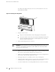
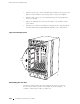
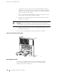
3. Prepare to lift the router:
One person stands behind t he chassis and grasps t he lifting handle.
Two people stand on either side of the chassis. Each grasps the bar at the
bottom of the FPC card cage with one hand and places the other hand
under the chassis near the rear.
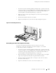
4. Lift the chassis and position it in the ra ck.
WARNING: To prevent injury, keep your back straight and lift with your legs, not
your back. Avoid twisting your body as you lift. Balance the load evenly and be
sure that your footing is solid.
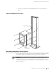
5. Align the bottom hole in both front support posts or center-mounting brackets
with a hole in each rack rail, making sure the chassis is level.
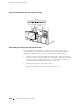
6. Install one of the mounting screws provided into each of the two aligned holes.
Use a 5/32-in. Allen wrench to tighten the screws.
7. Moving up each post or ear, install a screw in every mounting hole.
8. Verify that all the mounting screws on one side of the rack are aligned with the
mounting screws on the opposite side and that the router is level.
9. Loosenthethumbscrewsontheliftinghandleandremoveitfromthechassis.
98 In stalling the Chassis in to the Rack