
Internet Router Hardware Guide

M160 Internet Router Hardware Guide
Removing the Power Supplies
The router has two power supplies located at the bottom rear of the chassis, as
shown in Figure 2. A power supply weighs approximately 13 lb (5.9 k g).
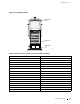
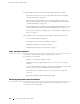
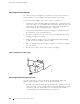
To remove the power supplies, follow this procedure (see Figure 32):
1. A tt ach an electrostatic discharge (ESD) grounding strap to your bare wrist and
connect the strap to one of the ESD points on the chassis. Make sure t he router
is attached to a proper earth ground. For more information about ESD, see
“Preventing Electrostatic Discharge Damage” on page 226.
2. Verify that the power switch for each power supply is in the OFF (O)position.
The switches are on the circuit breaker box.
3. Loosen the thumbscrew at each corner of the power supply faceplate, using
a Phillips screwdriver if necessary.
4. Grasp the handle or handles on the power supply faceplate and pull firmly
to slide the unit about halfway out of the chassis.
5. Place one hand under the power supply to support it, then slide it completely
outofthechassis.
6. Repeat the procedure to remove the second power supply.
Figure 32: Removing a Power Supply
g001918
Removi ng the Re ar Component Cover
The rear component co ver protects the SFMs, Routing Engines , MCSs, and
PCGs, as shown in Figure 2. To remove it, follow this procedure:
1. A tt ach an electrostatic discharge (ESD) grounding strap to your bare wrist and
connect the strap to one of the ESD points on the chassis. Make sure t he router
is attached to a proper earth ground. For more information about ESD, see
“Preventing Electrostatic Discharge Damage” on page 226.
86 Rem oving Components from the Chassis