
Network Router User Manual


Chapter 9
Connecting the Router
After installing the router into the rack as described in “Initial Installation” on page 39,
complete the installation by connecting management and alarm devices, PICs, and
power cables. This chapter has the following sections:
■ Tools and Parts Required on page 59
■ Connecting the Router to Management Devices on page 59
■ Connecting PIC Cables on page 61
■ Providing Power to the Router on page 62
Tools and Parts Required
To connect the router to management devices and PICs and to power on the router,
you need the following tools and parts:
■ Phillips (+) screwdrivers, numbers 1 and 2
■ Flat-blade (-) screwdrivers, 2.5 mm and 3 mm
■ Electrostatic damage (ESD) grounding wrist strap
Connecting the Router to Management Devices
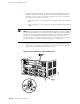
After you have installed the router into the rack, attach one or more external devices
to the ports on the craft interface that connect to the Routing Engine for management
and service operations (see Figure 22). For specifications for the cable accepted by
the Routing Engine management ports, see “Cable Specifications for Routing Engine
Management Interfaces” on page 187.
Figure 22: Routing Engine Management Ports
To connect external devices to the Routing Engine management ports, perform the
procedures described in the following sections:
■ Connecting to a Network for Out-of-Band Management on page 60
Tools and Parts Required ■ 59