
Network Router User Manual


Spacing of Mounting Holes
The holes in the mounting brackets are spaced at 1 U (1.75 in. or 4.45 cm), so the
router can be mounted in any rack that provides holes spaced at that distance.
Connection to Building Structure
Always secure the rack to the structure of the building. If your geographical area is
subject to earthquakes, bolt the rack to the floor. For maximum stability, also secure
the rack to ceiling brackets. For more information, see “Rack-Mounting Requirements
and Warnings” on page 155.
Clearance Requirements for Airflow and Hardware Maintenance
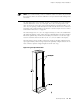
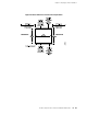
When planning the installation site, you need to allow sufficient clearance around
the rack (see Figure 16):
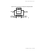
■ For the cooling system to function properly, the airflow around the chassis must
be unrestricted. Figure 9 depicts the airflow in the router. Allow at least 6 in.
(15.2 cm) of clearance between side-cooled routers. Allow 2.8 in. (7 cm)
between the side of the chassis and any non-heat-producing surface such as a
wall.
NOTE: We recommend that you do not install the router in a cabinet. If you mount
the router in a cabinet, be sure that ventilation is sufficient to prevent overheating.
■ For service personnel to remove and install hardware components, there must
be adequate space at the front and back of the router. At least 24 in. (61 cm) is
required both in front of and behind the router. NEBs GR-63 recommends that
you allow at least 30 in. (76.2 cm) in front of the rack and 24 in. (61 cm) behind
the rack.
44 ■ Clearance Requirements for Airflow and Hardware Maintenance
M10i Internet Router Hardware Guide