
Network Router User Manual


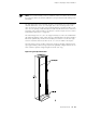


Table 14: Site Preparation Checklist (continued)
DatePerformed ByFor More InformationItem or Task
“Clearance Requirements for Airflow
and Hardware
Maintenance” on page 44
“Rack Size and Strength” on page 42
Plan rack location, including required space
clearances.
“Connection to Building
Structure” on page 44
If a rack is used, secure rack to floor and
building structure.
Cables
“Calculating Power Budget for
Fiber-Optic Cable” on page 185
“Calculating Power Margin for
Fiber-Optic Cable” on page 185
Acquire cables and connectors:
■
Determine the number of cables needed
based on your planned configuration.
■
Review the maximum distance allowed
for each cable. Choose the length of cable
based on the distance between the
hardware components being connected.
“Maintaining PICs and PIC
Cables” on page 74
Plan the cable routing and management.
Rack Requirements
The router must be installed in a rack. Many types of racks are acceptable, including
4-post (telco) racks and open–frame racks. An example of a open-frame rack appears
in Figure 15.
The following sections describe rack requirements:
■ Rack Size and Strength on page 42
■ Spacing of Mounting Holes on page 44
■ Connection to Building Structure on page 44
Rack Size and Strength
The router is designed for installation in a 19-in. rack as defined in Cabinets, Racks,
Panels, and Associated Equipment (document number EIA-310-D) published by the
Electronics Industry Association (http://www.eia.org).
With the use of adapters, the router is designed to fit into a 600-mm-wide and
600-mm-deep rack as defined in the four-part Equipment Engineering (EE); European
telecommunications standard for equipment practice (document numbers ETS 300
119-1 through 119-4) published by the European Telecommunications Standards
Institute (http://www.etsi.org). Use approved wing devices to narrow the opening
between the rails.
42 ■ Rack Requirements
M10i Internet Router Hardware Guide