
Network Router User Manual


■ 100-Mbps Fast Ethernet switch—Carries signals and monitoring data between
router components.
■
Two LEDs—Indicate HCM status. There is a green one labeled PWR and an blue
one labeled MSTR. Table 9 on page 18 describes the LED states.
■ Alarm LEDs—Display alarm conditions, if any exist.
■ PIC offline buttons—Relays a request to the CFEB, which prepares a PIC for
removal from the router, or brings the PIC online when it is replaced.
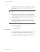
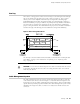
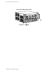
Figure 6: High-Availability Chassis Manager
Table 9: States for HCM LEDs
DescriptionStateColorLabel
HCM is functioning normally.On steadilyGreen
PWR
HCM is starting up.Blinking
HCM is master.On steadilyBlue
MSTR
Alarm LEDs
Two alarm LEDs are located on the right of the HCM (see Figure 6). The circular red
LED lights to indicate a critical condition that can result in a system shutdown. The
triangular yellow LED lights to indicate a less severe condition that requires monitoring
or maintenance. Both LEDs can be lit simultaneously.
To deactivate red and yellow alarms, you must clear the condition that caused the
alarm.
18 ■ High-Availability Chassis Manager (HCM)
M10i Internet Router Hardware Guide