
Network Router User Manual


■ I
2
C/EEPROM containing the serial number and revision level
■ Two 512-KB boot flash EPROMs (programmable on the board)
■ One PowerPC 8245 integrated processor
■
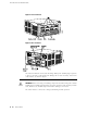
Three LEDs—A green LED labeled OK, a red LED labeled FAIL, and a blue LED
labeled MASTER indicate CFEB status. Table 7 on page 13 describes the LED
states.
■ Power off button—Prepares the CFEB for removal from the router when pressed.
■ Ejector levers—Control the locking system that secures the CFEB in the chassis.
NOTE: For specific information about CFEB components (for example, the amount
of SDRAM), issue the show chassis cfeb command.
Figure 4: CFEB
Table 7: States for CFEB LEDs
DescriptionStateColorLabel
CFEB is running normally.On steadilyGreen
OK
CFEB is starting up.Blinking
CFEB is not operational or is in reset mode.On steadilyRed
FAIL
CFEB is functioning as master.On steadilyBlue
MASTER
Compact Forwarding Engine Board (CFEB) ■ 13
Chapter 2: Hardware Component Overview