
Network Router User Manual


For further safety information, see “Safety and Regulatory Compliance
Information” on page 135.
Table 6 on page 9 summarizes physical specifications for the router chassis.
Table 6: Chassis Physical Specifications
ValueDescription
8.7 in. (22.1 cm)Chassis height
■
17.5 in. (44.5 cm) for sides of chassis
■
19 in. (48.3 cm) with mounting brackets
Chassis width
18 in. (45.7 cm)Chassis depth
79 lb (35.8 kg)Weight, maximum configuration
57 lb (25.9 kg)Weight, minimum configuration
■
AC: 3276 BTU/hour (960 W)
■
DC: 1965 BTU/hour (576 W)
Thermal output
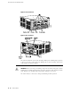
Midplane
The midplane is a panel located in the center of the chassis, running from side to
side and forming the rear of the PIC card cage (see Figure 3). All router components
plug directly into the midplane. The midplane contains an EEPROM that stores the
serial number and revision level of the midplane.
The midplane performs the following functions:
■ Transfer of packets—After being processed by a PIC, an incoming data packet
crosses the midplane to the CFEB. The CFEB performs switching and forwarding
functions and transfers outgoing packets back across the midplane to the PICs
for transmission to the network.
■ Power distribution—The midplane distributes power to all router components
from the power supplies attached to it. It also provides hot-plug protection for
the PIC and HCM slots.
■ Signal connectivity—The midplane transports the signals exchanged by system
components for monitoring and control purposes.
Midplane ■ 9
Chapter 2: Hardware Component Overview