
Network Router User Manual


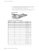


■ A V.35 connection requires an DB-25 to V.35 cable and connects to a V.35 data
terminal equipment (DTE) 34-pin Winchester type male cable (one per port).
Table 31 on page 204 describes the V.35 cable pinouts.
■ An X.21 connection requires an DB-25 to X.21 cable and connects to a X.21 DTE
DB-15 male cable. Table 32 on page 205 describes the X.21 cable pinouts.
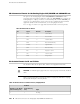
Figure 65: EIA-530 PIC
Table 31: DB-25 Connector to V.35 Connector Pinout
DescriptionV.35 PinSignalDB-25 Pin
Transmit DataPTD2
Transmit DataSTD14
Receive DataRRD3
Receive DataTRD16
Ready To SendCRTS4
Clear To SendDCTS5
Data Set ReadyEDSR6
Data Terminal ReadyHDTR20
DTE Transmit ClockUXTC24
DTE Transmit ClockWXTC11
Transmit ClockYTC15
Transmit ClockAATC12
Receive ClockVRC17
Receive ClockXRC9
Protective GroundAFGND1
Signal GroundBGND7
204 ■ X.21 and V.35 Cable Pinouts for EIA-530 PIC
M10i Internet Router Hardware Guide