
Network Router User Manual


for seven connectors (0.5 dB per connector, or 3.5 dB). The power margin (P
M
) is
calculated as follows:
P
M
= P
B
– LL
P
M
= 13 dB – 8 km (0.5 dB/km) – 7 (0.5 dB)
P
M
= 13 dB – 4 dB – 3.5 dB
P
M
= 5.5 dB
In both examples, the calculated power margin is greater than zero, indicating that
the link has sufficient power for transmission and does not exceed the maximum
receiver input power.
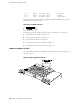
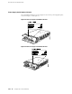
Cable Specifications for Routing Engine Management Interfaces
For management and service operations, you connect the Routing Engine to an
external console or management network through ports on the craft interface. For
information about the ports, see “Routing Engine Interface Ports” on page 16.
Table 24 on page 187 lists the specifications for the cables that connect to management
ports.
Table 24: Cable Specifications for Routing Engine Management Interfaces
Router
Receptacle
Maximum
Length
Cable/Wire
Supplied
Cable
SpecificationPort
DB-9 male6 ft (1.83 m)One 6-ft (1.83-m)
length with
DB-9/DB-9
connectors
RS-232 (EIA-232)
serial
Routing Engine
console or
auxiliary
interface
RJ-45
autosensing
328 ft (100 m)One 15-ft (4.57-m)
length with
RJ-45/RJ-45
connectors
Category 5 cable or
equivalent suitable
for 100BaseT
operation
Routing Engine
Ethernet
interface
Cable Specifications for Routing Engine Management Interfaces ■ 187
Appendix D: Cable Specifications