
Network Router User Manual


c. Pull the cable connector straight out of the port.
d. Disconnect the cable from the console or auxiliary device.
2.
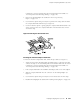
Plug the female end of the replacement serial cable into the appropriate CONSOLE
or AUX/MODEM port. Figure 52 shows the external device ports on the Routing
Engine.
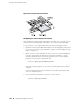
3. Tighten the screws on the connector, using a 2.5-mm flat-blade screwdriver if
necessary.
4. Power on the auxiliary or console device.
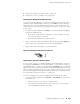
Figure 54: Console and Auxiliary Serial Port Connector
132 ■ Replacing Routing Engine Components
M10i Internet Router Hardware Guide